


Question:
For the direction of internal forces, there are four options for smoothing the internal forces under the "Grouped" selection box. Which grouping should I select here?
Answer:
The "Grouped" determination of internal forces is divided into four subcommands.
1.
u with m-y,m-xy,v-y,n-y,n-xy
2.
v with m-x,m-xy,v-x,n-x,n-xy
3.
u with m-x,m-xy,v-x,n-x,n-xy
4.
v with m-y,m-xy,v-y,n-y,n-xy
The effect of these commands is explained using a simple example.
Structure:
Plate as a deep beam
Span 9 m
Beam height 1.5 m
Concentrated load 20 kN in the middle of the span
FE mesh size 10 cm
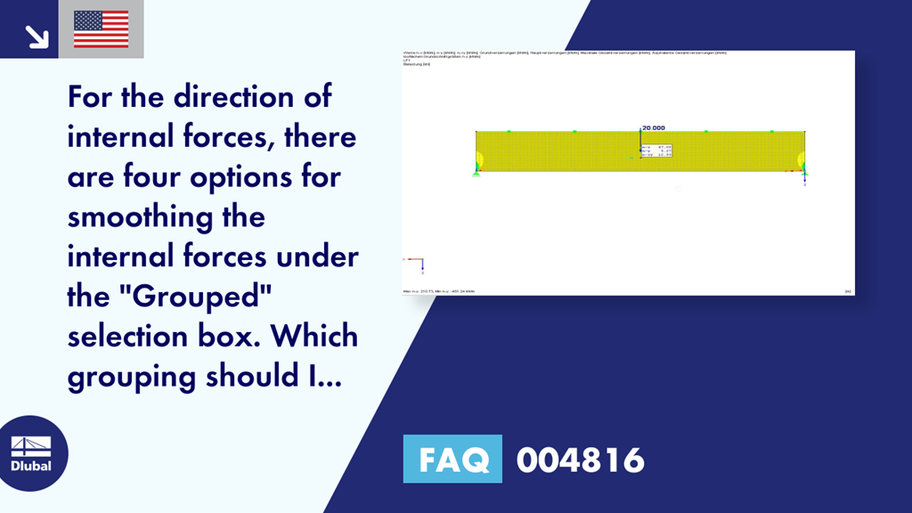
Image 01 shows the maximum and minimum internal forces at the load application point in an unsmoothed state. Obviously, these internal forces are singular results. You can find detailed information about singularities in Technical Article 001503.
In order to completely include at least two FE elements for each side of the load introduction using the average region, an average region of 50/50 cm is defined (Image 02).
The following table shows the change of smoothing separately for each grouping. For this, only the drawn upper region of the load application is considered. Grouping 0 stands for the unsmoothed internal forces in this case.
0 - 1 - 2 - 3 - 4
n-x - 74.9 kN/m - 74.9 kN/m - 47.2 kN/m - 51.8 kN/m - 74.9 kN/m
n-y - 109.0 kN/m - 26.5 kN/m - 109.0 kN/m - 5.8 kN/m
n-xy - 75.1 kN/m - 30.7 kN/m - 15.8 kN/m - 30.7 kN/m - 15.8 kN/m
The table shows that a combination of Grouping 1 and Grouping 2, as well as Grouping 3 and Grouping 4, is always reasonable in relation to the axial forces.
Image 03 shows the averaged internal forces for Groups 1/2 and 3/4 together.
The following values are used for the combinations:
1/2 - 3/4 - 1/2 and 3/4
n-x - 47.2 kN/m - 51.8 kN/m - 47.1 kN/m
n-y - 26.5 kN/m - 5.8 kN/m - 5.3 kN/m
n-xy - 12.9 kN/m - 12.9 kN/m - 12.9 kN/m
As already mentioned, combinations 1/2 and 3/4 use the minimum average internal forces of the respective grouping. The shear force n-xy is calculated from the forces in the normal direction; therefore, it is already displayed as "smeared shear force" for combinations 1/2 and 3/4.
Conclusion
For a material with distinct stiffness and strength directions, such as reinforced concrete or cross-laminated timber, the orientation of the strengths is relevant for the selection of the correct grouping. In the combination of Group 1/2, the internal forces are averaged in the longitudinal direction of the structural component; in Group 3/4, in the transverse direction. If the structural component is oriented in the longitudinal direction as shown in Image 04, we therefore recommend smoothing in the longitudinal direction. However, the type of load application and the governing design are also important here. All groupings can be used for an isotropic material as well as for the governing shear force design.