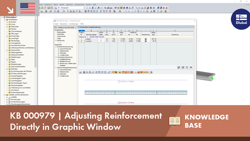
It is possible to edit a reinforcement layout or an existing reinforcement directly in the reinforcement's 3D rendering.
KB 000979 | Adjusting Reinforcement Directly in Graphic Window
The reinforcement proposal from RF-/CONCRETE Members can be exported to Revit. The rectangular and circular cross-sections are currently supported.
The reinforcement bars can be modified retroactively in Revit.
Do you have individual column sections and angled wall geometries, and need punching shear design for them?
No problem. In RFEM 6, you can perform punching shear design not only for rectangular and circular sections, but for any cross-section shape.
The Concrete Design add-on provides you with the option to perform the simplified fire resistance design according to EN 1992‑1‑2 for columns (Section 5.3.2) and beams (Section 5.6).
The following design checks are available for the simplified fire resistance design:
- Columns: Minimum cross-sectional dimensions for rectangular and circular sections according to Table 5.2a as well as Equation 5.7 for calculating time of fire exposure
- Beams: Minimum dimensions and center distances according to Table 5.5 and Table 5.6
You can determine the internal forces for the fire resistance design according to two methods.
- 1 Here, the internal forces of the accidental design situation are included directly into the design.
- 2 The internal forces of the design at normal temperature are reduced by the factor Eta,fi (ηfi), then used in the fire resistance design.
Furthermore, it is possible to modify the axis distance according to Eq. 5.5.
With the Concrete Design add-on, you can perform the fatigue design of members and surfaces according to EN 1992‑1‑1, Chapter 6.8.
For the fatigue design, you can optionally select two methods or design levels in the design configurations:
- Design Level 1: Simplified design according to 6.8.6 and 6.8.7(2): The simplified design is performed for frequent action combinations according to EN 1992‑1‑1, Chapter 6.8.6 (2), and EN 1990, Eq. (6.15b) with the traffic loads relevant in the serviceability state. A maximum stress range according to 6.8.6 is designed for the reinforcing steel. The concrete compressive stress is determined by means of the upper and lower allowable stress according to 6.8.7(2).
- Design Level 2: Design of damage equivalent stress acc. to 6.8.5 and 6.8.7(1) (simplified fatigue design): The design using damage equivalent stress ranges is performed for the fatigue combination according to EN 1992‑1‑1, Chapter 6.8.3, Eq. (6.69) with the specifically defined cyclic action Qfat.