Answer:
As soon as a new node is selected for the design, the geometry is reimported from the main program RFEM 5 or RSTAB 8, and the default values of the connection are preset.
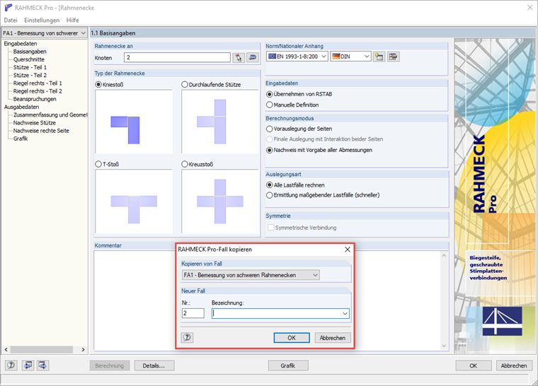
We recommend copying the design case in the event that another modification of the previously defined connection will be considered. If you want to design two nodes with the same geometry, you should select them both at the beginning.