The structural analysis software RFEM 6 is the basis of a modular software system. The main program RFEM 6 is used to define structures, materials, and loads of planar and spatial structural systems consisting of plates, walls, shells, and members. The program also allows you to create combined structures as well as to model solid and contact elements.
RSTAB 9 is a powerful analysis and design software for 3D beam, frame, or truss structure calculations, reflecting the current state of the art and helping structural engineers meet requirements in modern civil engineering.
Do you often spend too long calculating cross-sections? Dlubal Software and the RSECTION stand-alone program facilitate your work by determining section properties of various cross-sections and performing a subsequent stress analysis.
Do you always know where the wind is blowing from? From the direction of innovation, of course! With RWIND 2, you have a program at your side that uses a digital wind tunnel for the numerical simulation of wind flows. The program simulates these flows around any building geometry and determines the wind loads on the surfaces.
Are you looking for an overview of snow load zones, wind zones, and seismic zones? Then you are in the right place. Use the Geo-Zone Tool to determine quickly and efficiently snow loads, wind speeds, and seismic data according to ASCE 7‑16 and other international standards.
Would you like to try out the capabilities of the Dlubal Software programs? You have the opportunity to do so! The free 90-day full version allows you to thoroughly test all our programs.
The following computer configurations are required as a minimum for RFEM 6 and RSTAB 9:
RFEM 6 and RSTAB 9 currently do not run on Linux or Mac OS.
For optimal program capabilities, the following computer configuration is recommended:
If you use an Nvidia card on a remote computer, you may have to install an additional tool from Nvidia to enable remote accelerated OpenGL:
https://developer.nvidia.com/nvidia-opengl-rdp
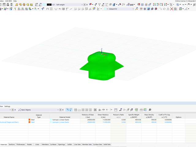
This can happen if you have a node that is very far away from the main structure. It is recommended that you set the view to "Isometric" and then this will zoom out on your model and give you an idea of where these stray elements are located.You will need to delete these elements that are not attached to the structure or move them closer.Note: Enlarged graphical issues can happen when importing a model from another format and the structure is extremely far away from the origin. The solution to this is to move the model as close as possible to the origin.
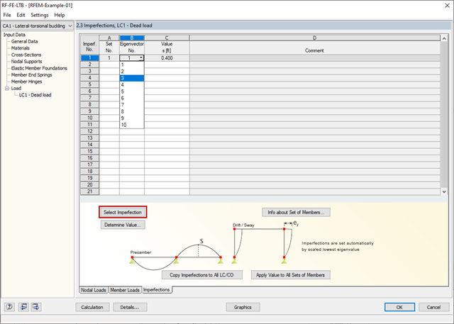
According to EN 1993‑1‑1 and DIN 18800 Part 2, it is necessary to specify the equivalent geometric imperfections for the second-order analysis to determine the geometric and structural imperfections as well. This pre-deformation should be applied as affine to the lowest buckling or lateral-torsional buckling mode.
Therefore, in the FE‑LTB program, the eigenvalue belonging to the smallest mode shape is calculated (preliminary eigenvalue analysis) and then selected as the initial deformation mode. The imperfection approach is then carried out by the user scaling the mode shape.
Thus, the pre-deformation is based on the mode shape in RF‑/FE‑LTB. The imperfections defined in RFEM/RSTAB are irrelevant and are therefore not adopted.
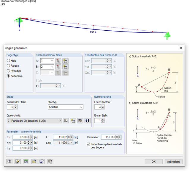
Yes, it is. Cables only absorb tension forces. This allows cable chains to be calculated taking longitudinal and transverse forces into account. To do this, it is necessary to define the complete cable as a cable chain consisting of several cable members. It is possible to create the chain lines quickly, using the menu "Tools → Generate Model → Arc". The more precisely the initial shape of the chain line matches the real cable chain, the more stable and faster the calculation can be.
We recommend prestressing the cable members. This way, compressive forces that would lead to failure will be prevented. Cables should also be used only if the deformations make a significant contribution to the changes in the internal forces; that is, if large deformations may arise. For simple, straight riggings like transverse bracings, tension members are completely sufficient.
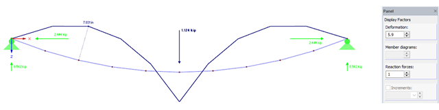
When evaluating deformations of cable members, set the scaling factor in the control panel to "1" so that the tightening effects are represented close to reality.
The large deformation analysis ("third-order theory") takes longitudinal and transversal forces into account during the analysis of internal forces. In the analysis, the stiffness matrix is created for the deformed system after each iteration step.
Member loads that have been defined as local are currently handled in such a way that the load direction is the same as for the undeformed system. All internal forces are transformed to the deformed member axis systems. Members of the "Cable" member type are always calculated according to the large deformation analysis. The remaining members will be treated according to the selected method of analysis.
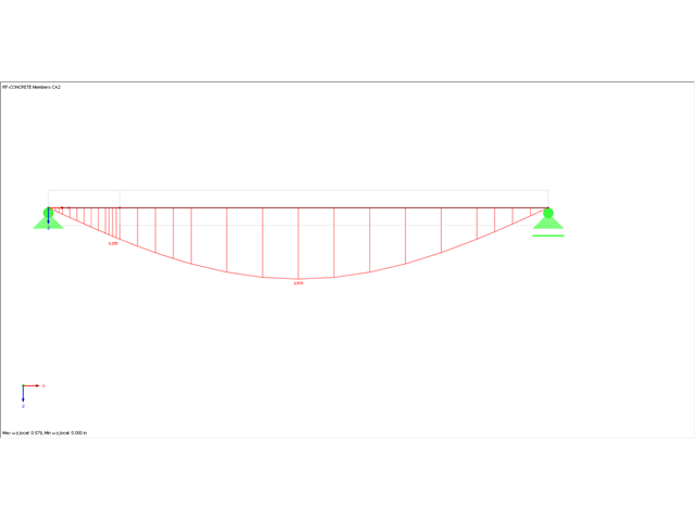
The scaling of the internal forces line - that is, the sizes of the parabolic lines - can be set in the window of the result control panel in the Display Factors tab.
You can open the control panel using the menu "View" → "Control Panel" or using the button of the same name (see image).
In this window, you can set the display factors for all displayed results.
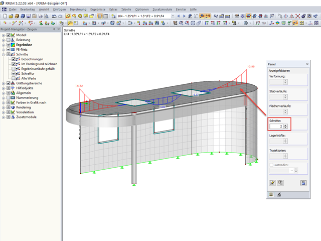
This unusual representation is due to the display factor for the deformations. If you set this factor to 1, you obtain realistic deformation without scaling.
The factor can be specified in the panel. The panel appears as soon as the results are available. You can also display it using the menu "View → Control Panel".
With the factor of 1, it is obvious that the force in the middle results in stretching of the cable. This stretching leads to an upward shifting of the outer nodes.