How does the flattening process consider the compensation in the determination of cutting patterns?
Answer
The flattening process in the RF‑CUTTING‑PATTERN add-on module is an iterative process that flattens the respective areas of a cutting pattern by minimizing the distortion energy assuming the assigned material behavior.
In simplified terms, the method compresses the initial geometry in a press assuming a frictionless contact until the stresses due to flattening are in equilibrium with each other.
→ See the video
Since this process covers the complete mechanics of the curved structural component, you it is possible to additionally consider the compensation directly as an applied strain load.
Figure 01 - Compensation
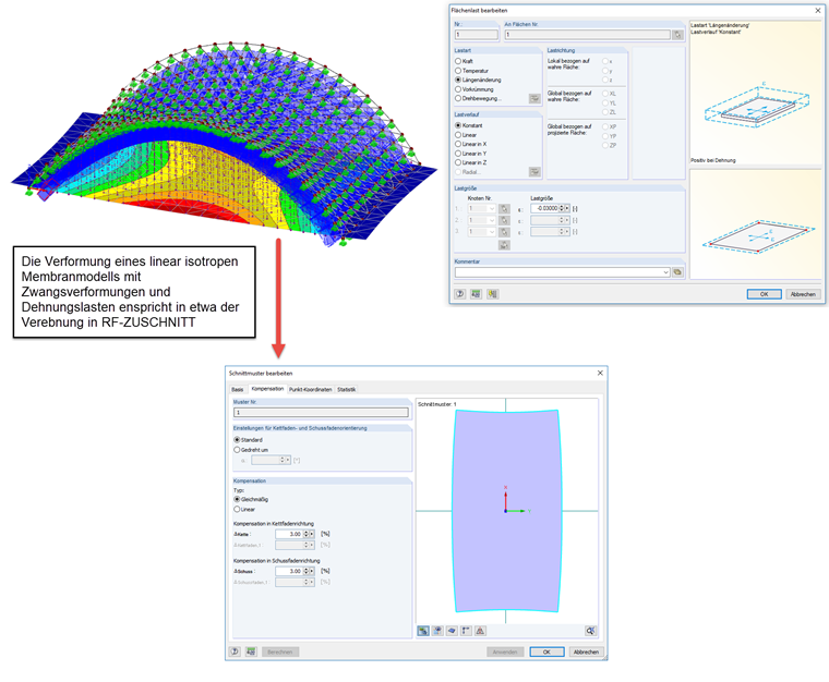
Since the strains from the compensation specification interact with the strains from the flattening in the algorithm of RF‑CUTTING‑PATTERN, this kind of compensation consideration cannot be compared with the usual, flat scaling of the non-compensated cutting patterns. The consideration of the complete "cutting pattern mechanics" with all strain terms provides very high-quality geometry of the cutting pattern.
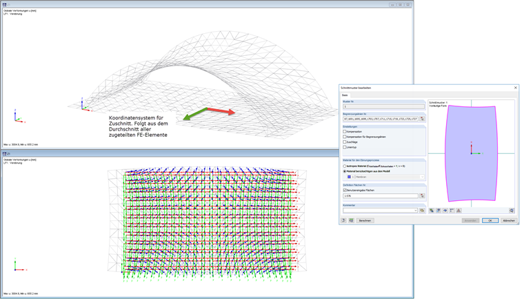
Keywords
Cutting pattern Energy Minimum Quality Curvature Compensation Relaxation
Downloads
Contact us
Did you find your question?
If not, contact us via our free e-mail, chat, or forum support, or send us your question via the online form.
Recommended Events
Membrane Structures with Wind Loads From CFD Wind Simulation
Webinar 24 March 2020 3:00 PM - 4:15 PM CET
Videos
Models to Download
Knowledge Base Articles

The RF‑FORM‑FINDING add‑on module can be activated in the ‘Edit Model - General Data’ window, ‘Options’ tab. By activating the module, a new RF‑FORM‑FINDING load case is created and an additional menu appears in the main program, allowing for the definition of prestress conditions for membrane and cable elements.
Screenshots
Product Features Articles
- Planar and geodesic cutting lines
- Flattening of double-curved surface parts of tensioned membranes or pneumatic cushions
- Definition of cutting patterns by using boundary lines which are not required to be connected
- Sophisticated flattening based on the minimum energy theory
- Welding and boundary allowances
- Uniform or linear compensation in warp and weft direction
- Possibility of different compensations for boundary lines
- Adaptable data organisation (any additional modification of input data is considered up to the final "weld")
- Graphic display of cutting patterns
- Statistical information about each cutting pattern (width, length, size)
- Option to automatically generate cutting patterns from cells
Frequently Asked Questions (FAQ)
- How can I define a material allowance at the edge of a cutting pattern?
- How is it possible to create the cutting pattern geometry for a decorative sticker on a biaxially curved membrane roof?
- How are the properties of the elasticity and shear modulus of a membrane fabric with the usual force/length syntax transformed into the general force/surface syntax to be entered in RFEM?
- Why does the direction of a cutting pattern edge line in the support area change abruptly?
- How do I recognize that the flattening process in RF‑CUTTING‑PATTERN has found the convergence?
- How can I smooth continuous boundary lines of membrane cuttings?
- By which length is the boundary line compensation distributed in the surface?
- Why is the compensated cutting pattern length of a membrane surface incompatible with the defined compensation?
- How do I model a tent roof with two cone tips?
- I would like to calculate and design "temporary structures." What do I need for this?
Customer Projects