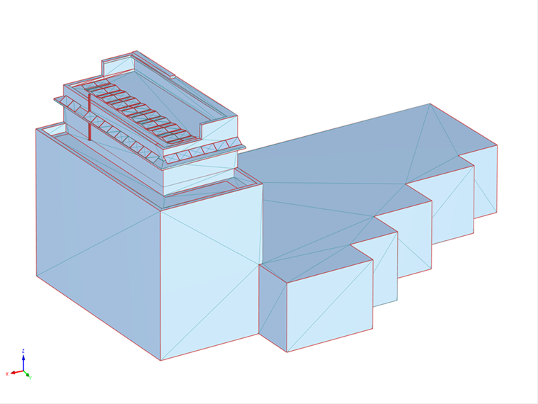
Given the multiple dimensional scales of large models, partitioning into smaller parts and local access is required. In the following, you will see how to split the model into parts, set the mesh details, and use mesh refinement and zones. This will be shown on the example shown in Image 01, which is a building with solar panels on its roof. We will focus on the wind load acting on the panels, and you will see the following:
- Splitting the model into parts
- Defining the model simplification settings
- Assigning zones to parts of the model
- Checking the generated shrink-wrapping mesh
- Examining the results on zones
Splitting Model into Parts
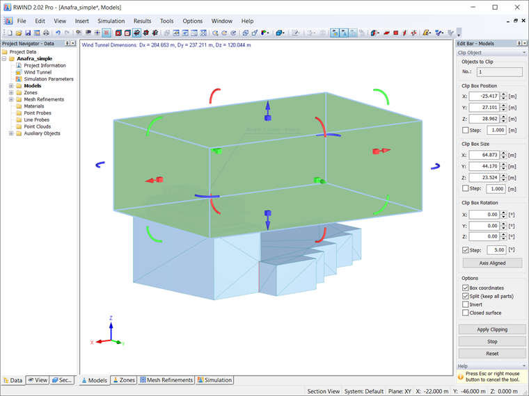
Splitting a large model into parts allows us to manually adjust the quality of the mesh for each part, optimizing the next generated shrink-wrapping mesh and simulating it according to our needs. To split the model into parts, you should use the "Clip Object" option (Image 02).
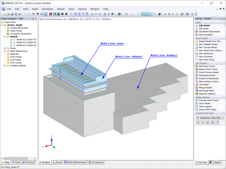
The breakdown itself should be based on your requirements and needs and relate to the part of the model that interests you the most. In this case, these are the solar panels on the roof. Therefore, the model is divided into three parts: model No. 1, which includes only the panels, model No. 2, which is the roof under the panels, and model No. 3, which is the rest of the model (Image 03). Please note that model No. 2 is being introduced to allow for smooth transitions between fine mesh and coarse mesh.
Model Simplification Settings
The next step is to set the appropriate level of detail for the building parts. This can be done in the “Edit Model” window shown in Image 04. Since the solar panels (that is, Model 1) are the focus of our interest, the goal is to make this model as accurate as possible in order to best model the wind loading. The detail scale (1-4) might not be enough, and so we can use "Detail size" and enter the value manually.
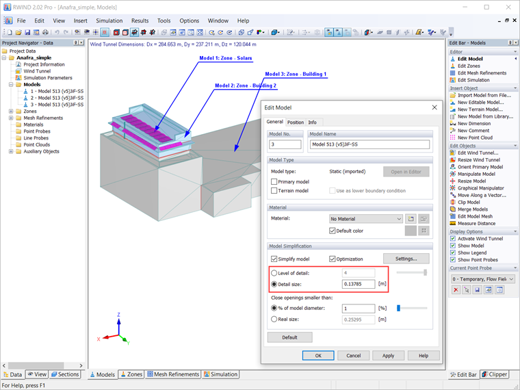
The level of detail is therefore set in descending order: from model 1, which we want to be as precise as possible, is assigned the highest level of detail, to rough model 3, which interests us the least. Model 2, which connects the most accurate model with the rough model, is assigned a medium level of detail, since we want to achieve good continuity in the subsequently generated shrink-wrapping meshes.
You must take into account that the detail size is not universal and depends on the computational model and the phenomenon being studied. Each problem must be approached individually, critically considering what part of the model you are interested in, the size of the entire model, the available computing power, and the time. Now you might think that a model that is as detailed as possible is the best option because it will cover all the details of the model. This is only partially true; a high level of accuracy covers all the details of the model, but can be very demanding (in some cases even unpredictable) in terms of computational hardware or very time consuming. Therefore, you need to choose the detail size considering all the things we just discussed.
Please note that if you don’t simplify the model, the program sends an exact model to the simulation without shrink wrapping, the calculation is then based on the exact geometry and can be very computationally intensive. In this case, the model must be geometrically correct (it must not contain open edges and non-manifold edges), which requires geometry correction in CAD programs. RWIND also includes a geometry correctness check. If the model is not correct after turning off the simplification, we get a warning message, but if we continue the calculation, we can expect errors or invalid results.
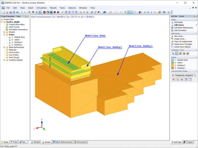
Assigning Zones to Parts of Model
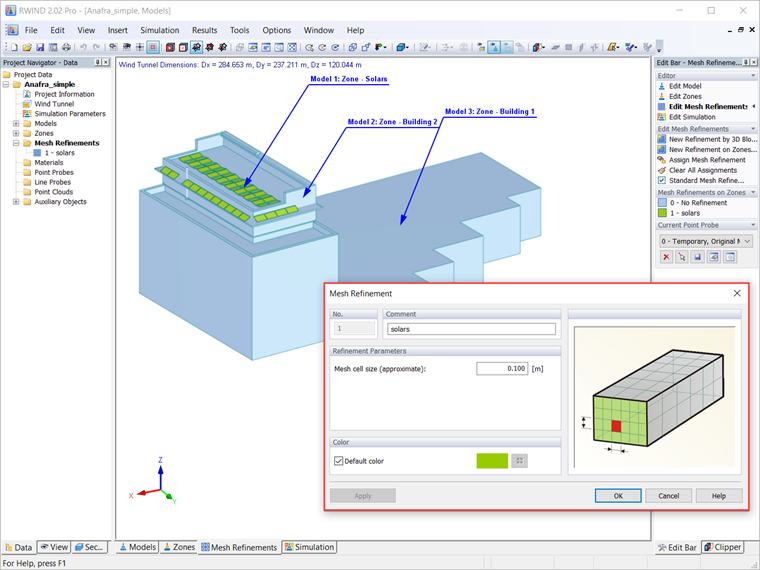
As mentioned earlier, the model has been divided into separate parts (models) as shown in Image 05. At this point, you can assign zones to the models for even more accurate results. This allows you to apply local mesh refinements as shown in Image 06. Please note that in order to get the best possible mesh, a mesh refinement should be assigned to the part of the model that interests you the most. In this example, this is the first part, that is, model No. 1 (Image 06).
Checking Generated Shrink-Wrapping Mesh
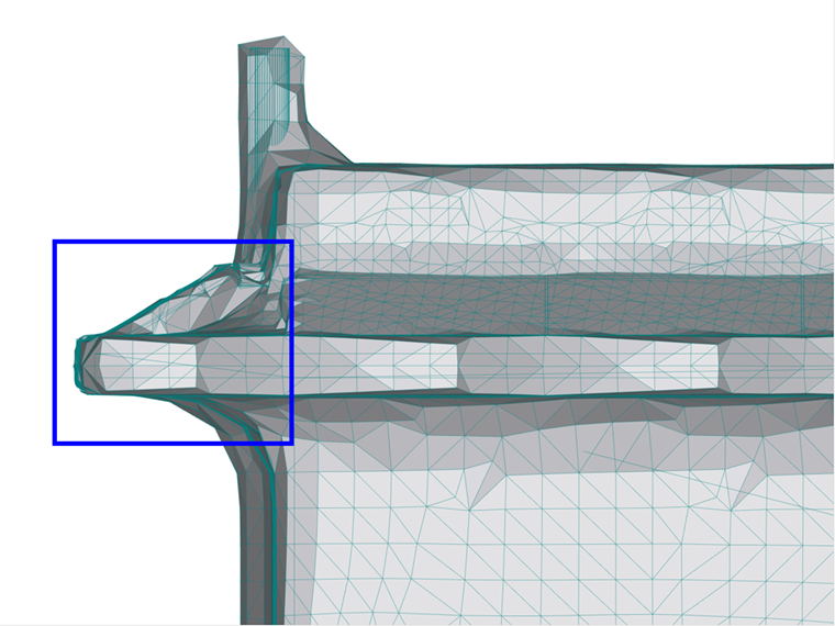
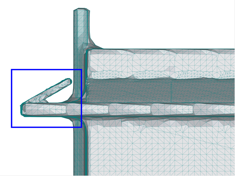
After applying a mesh refinement, you should review the generated mesh. This should be done taking into account the need to achieve smooth mesh transitions between the individual parts of the model. The shrink-wrapping mesh generated for the model in this article is shown in Image 07.
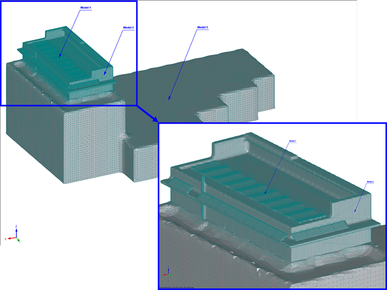
In this example, we would like to check that the shrink-wrapping mesh hasn't wrapped the parts of the model to flow around in the simulation, i.e., the solar panels on the roof. The goal is to have mesh around the panels that is fine enough to have all the important details. If this is not the case, you must choose a smaller detail size, regenerate the mesh, and check it again.
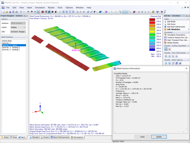
Results for Zones
Finally, you should take a look at the results for the zones obtained with the calculation. They are shown in Image 10 and contain all flow results of pressures, velocities, Cp coefficients, and so on, as well as geometric data of the area.