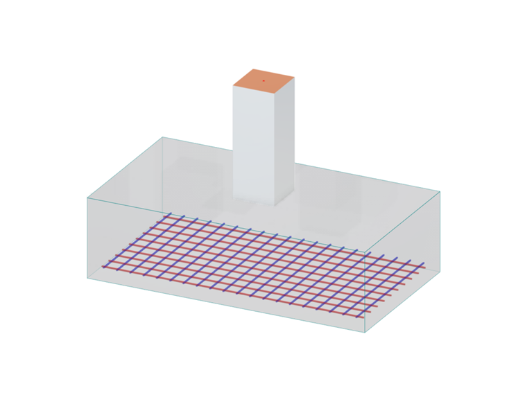
Foundation design can generally be divided into two parts: geotechnical design and reinforced concrete design. Geotechnical design focuses on the interaction between the footing and the supporting soil. It includes verification of soil bearing pressure as well as checks for uplift, overturning, and sliding using Allowable Stress Design (ASD). Reinforced concrete design includes flexural design, one-way shear, two-way (punching) shear, and reinforcement detailing according to Strength Design (LRFD).
Modeling the Pad Foundation
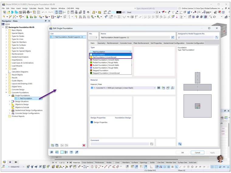
A nodal support must first be assigned to the column before a foundation can be defined. Several foundation types are available in the drop-down menu (Image 2). For the ACI standard, only the pad foundation is currently supported. The remaining foundation types will be available in future releases. The footing dimensions, concrete cover, and reinforcement are specified in the subsequent tabs.
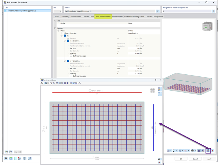
Under the Plate Reinforcement tab, the reinforcement bar size and spacing are defined. The resulting number of reinforcing bars is displayed in the reinforcement layout (Image 2).
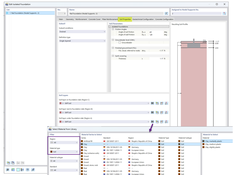
Under the Soil Properties tab, the groundwater level and earth covering are specified (Image 3). The available soil materials serve primarily as templates, allowing properties such as the unit weight and friction angle to be modified as needed.
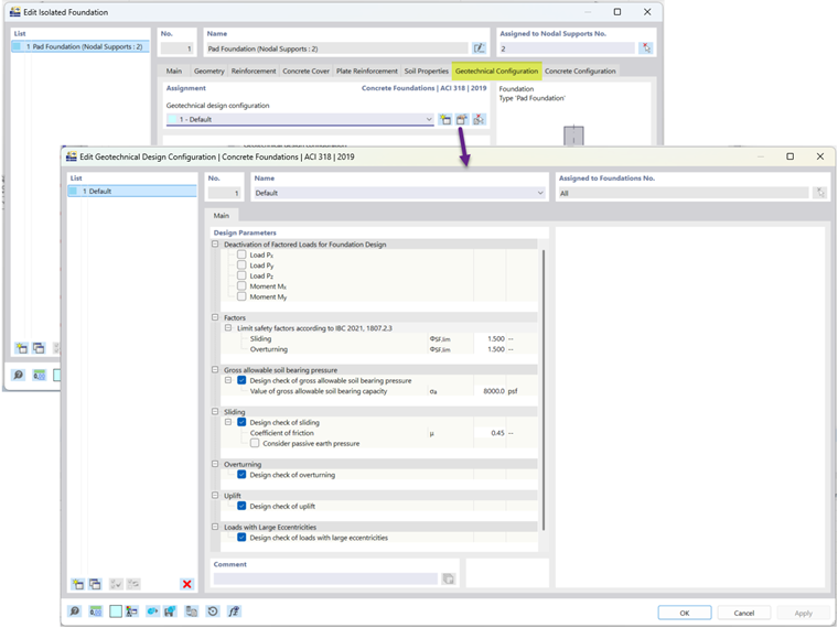
Under the Geotechnical Configurations tab, the gross allowable soil bearing pressure and the coefficient of friction can be specified (Image 4).
Example
Foundation Example 4 from the ACI Concrete Design Handbook [3] is used to verify the results obtained from the RFEM model. The example considers a rectangular spread footing measuring 5.5 ft × 10.0 ft × 2.833 ft supporting an 18-inch square column.
The bottom of the footing is located 4 ft below the finished grade, resulting in an earth covering height of:
4.0 ft − 2.833 ft = 1.167 ft
The option to include the earth covering is available under the Load Cases tab (Image 5), while the earth covering height is entered under the Soil Properties tab (Image 3).
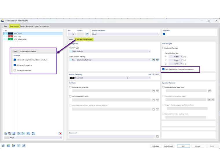
This example focuses only on the controlling load combination D + L + W using the provided net allowable soil bearing pressure of 8,000 psf. In RFEM, the gross allowable soil bearing pressure is specified because this is more common in current geotechnical reports.
The applied loads, material properties, and reinforcement layout are shown in Image 6.
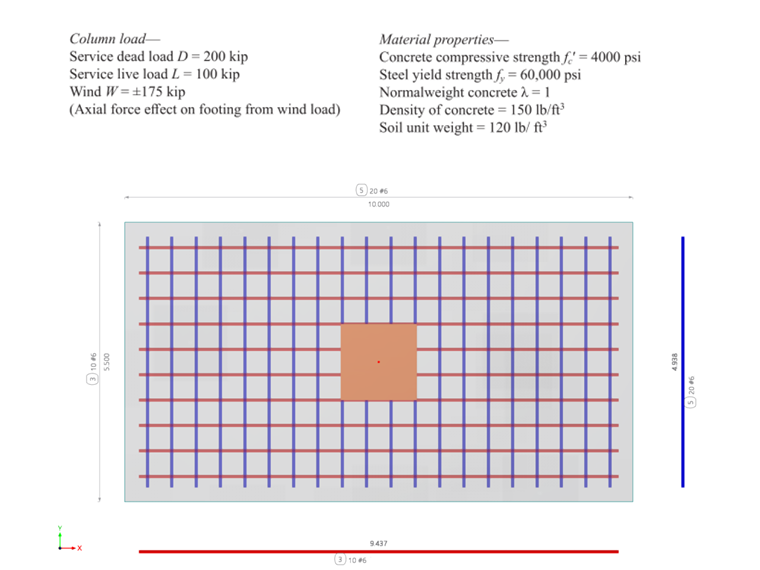
For geotechnical design, the ACI example assumes an increased allowable bearing pressure using the load combination D + L + 0.6W, where the live and wind loads are not reduced by the 0.75 factor typically applied to ASD load combinations. To match the ACI example, a user-defined load combination is therefore created in RFEM.
Results
After running the Concrete Foundations calculation, the results are displayed in the Design Ratios on Nodes table. The minimum flexural reinforcement checks are presented in the Reinforcement on Foundation table, while the Not Covered Reinforcement by Node tab summarizes any locations with insufficient reinforcement (Image 7).
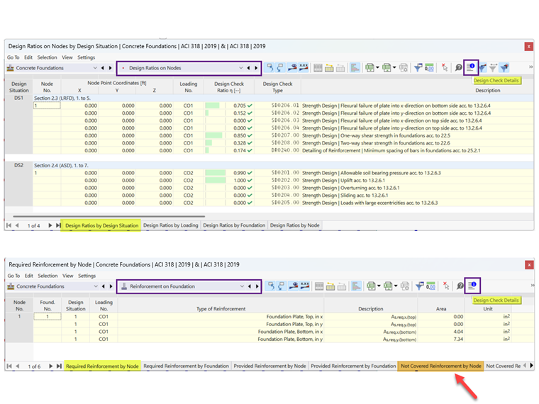
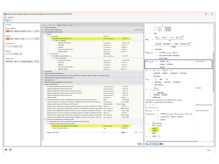
The design check detail includes the governing equations and references to the corresponding provisions of ACI 318 (Image 8).
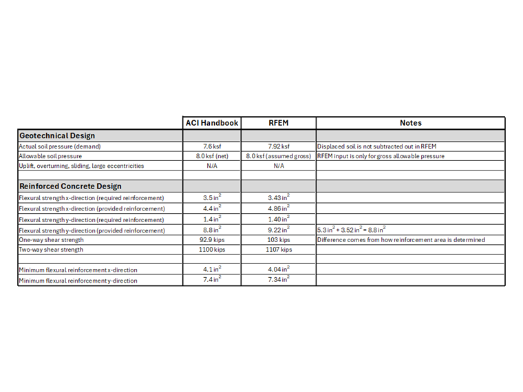
The results from the ACI Concrete Design Handbook and RFEM are summarized in the table shown in Image 9.
Conclusion
The Concrete Foundations add-on enables the design of rectangular isolated footings in accordance with ACI 318 and IBC within RFEM 6. The verification example demonstrates close agreement between the RFEM results and the ACI Concrete Design Handbook, confirming the accuracy of the implemented geotechnical and reinforced concrete design procedures. With integrated checks for bearing pressure, stability, flexure, and shear, the add-on provides an efficient workflow for isolated footing design, while additional features such as development length and dowel design are planned for future releases. Together with its member and base plate design capabilities, RFEM 6 provides a complete workflow for designing the entire structure within a single model.