Purpose
Tapers are members with a cross-section that varies in height. In steel structures, they are primarily used in frame structures at frame joints, where the moment distribution increases sharply. A cross-section distribution adapted to the moment distribution allows for efficient structures.
The general procedure for modeling tapers is shown in the following FAQ:
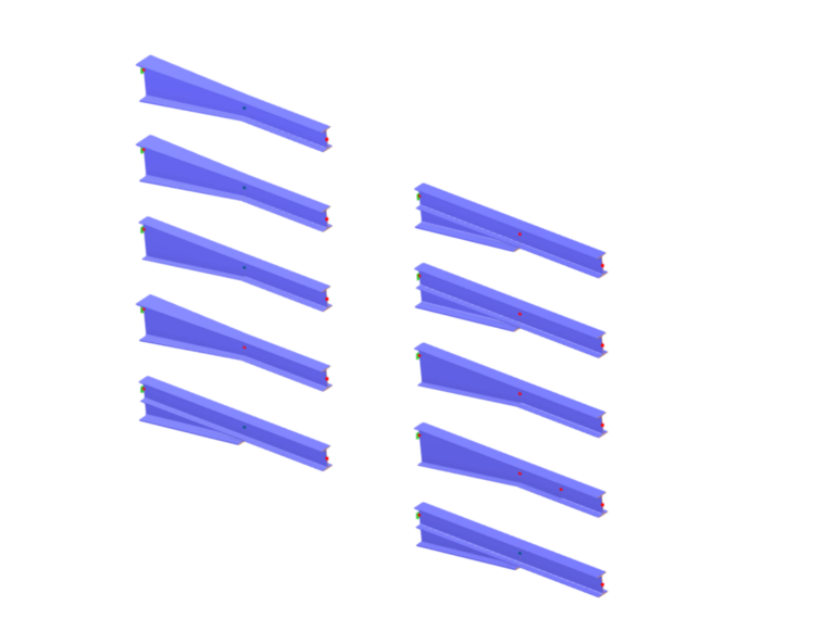
In the following, the modeling of various variants is demonstrated using RFEM 6. The following image shows an overview of the variants.
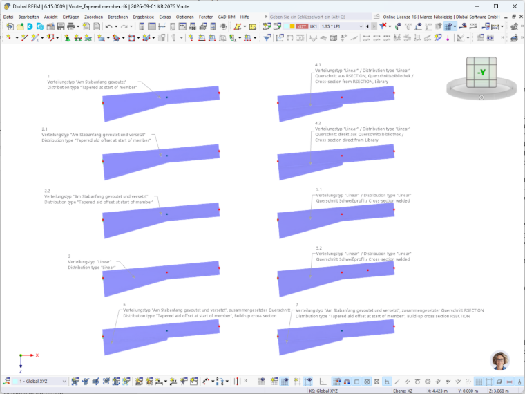
Variant 1: Distribution Type “Tapered at Start of Member”
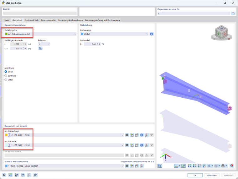
A beam is defined using the “Tapered at start of member” distribution type. An IPE 450 is used at the member start, and an IPE 240 at the member end. The standard sections are taken from the cross-section library. RFEM interpolates both cross-sections. A notable feature here is that the taper is interpolated not only in height but also in the width of the beam, from B1 = 190 mm to B2 = 120 mm.
For practical applications in steel structures, it is particularly important to note that the plate thicknesses of the web (tw) and flanges (tf) are also interpolated. This cannot be accurately represented in reality.
The input in the program is initially made by selecting the “Tapered at start of member” distribution type. The cross-sections are defined at the member start (Point i) and at the member end (Point j). An input at the inner point k is not possible with this variant. For this distribution type, a node of the “On Member” type is generated at the inner point k—that is, at the transition from the tapered section to the parallel-flanged section.
Variant 2.1: Load Distribution Type “Tapered and Offset at Start of Member”
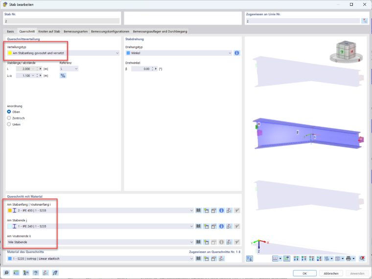
A beam is defined using the “Tapered at start of member and offset” distribution type. The remaining inputs correspond to those in Variant 1.
Input in the program: The cross-sections are defined at the member start (Point i) and at the member end (Point j). An input at the inner point k is possible in this variant, but is not used here for a separate input. Thus, from a structural analysis point of view, Variant 2.1 corresponds to Variant 1.
Variant 2.2: Distribution Type “Tapered and Offset at Start of Member”
A beam is defined using the “Tapered and offset at start of member” distribution type. Unlike Variant 2.1, the cross-sections for the taper are not taken as rolled sections from the cross-section library, but are defined as “Parametric – Thin-walled” cross-sections with the “Welded” manufacturing type. The dimensions correspond to the IPE 450 and IPE 240 used in the above-mentioned variants, but without rolling radii. The cross-section outside the taper is defined as an IPE 240 rolled section for the member end j. Due to the cross-section change at the taper end k, an input is required here.
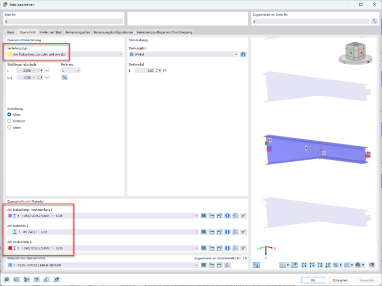
Variant 3: Distribution Type “Linear”
The tapered member (“Linear” distribution type) and the member with a parallel-flange cross-section (“Uniform” distribution type) are entered separately. For the design, both members are combined into a single member set. Thus, from a structural design perspective, Variant 3 corresponds to Variant 1.
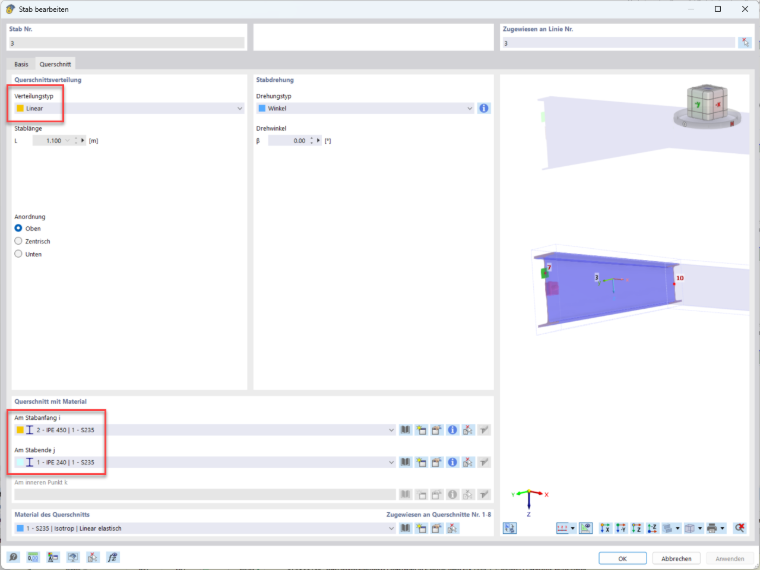
Variant 4.1: Distribution Type “Linear”, Built-up Cross-Section from RSECTION 1
The tapered member (“Linear” distribution type) and the member with a parallel-flange cross-section (“Uniform” distribution type) are entered separately. For the design, both members are merged into a single member set. The cross-sections for the tapered member are generated in RSECTION 1. The cross-section type is a composite cross-section consisting of an IPE 240 and a residual cross-section of an IPE 450 with variable height. The maximum total height of the taper is set to 450 mm; the minimum height is approximately 280 mm. The cross-section definition is explained below in Variant 4.2.
Unlike the variants mentioned above, this taper is not variable in either width or plate thickness. The lower flange of the IPE240 extends along the entire length of the taper.
Note that at the end of the taper, the height cannot be reduced to 240 mm (here at Joint No. 13). The reason for this is that the program needs to find cross-sections at the start and end of the member where the number of stress points matches.
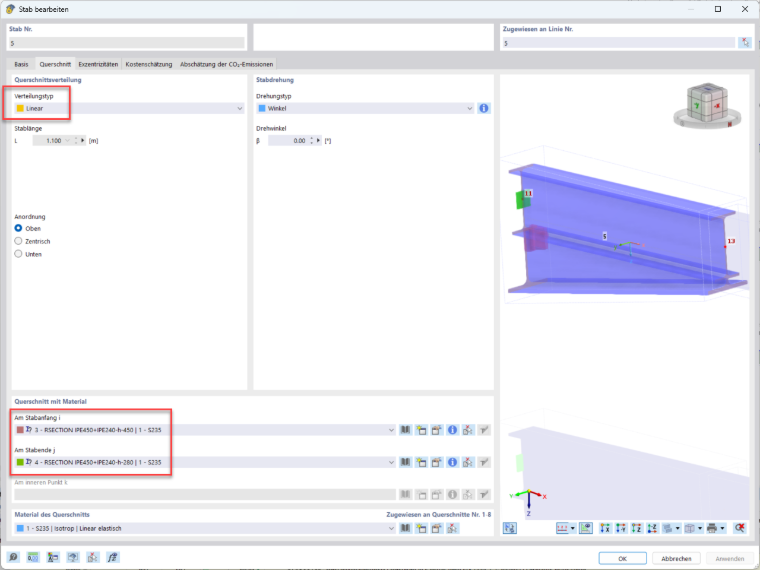
Variant 4.2: Distribution Type “Linear”, Built-up Cross-Section from RFEM 6
Variant 4.2 corresponds to Variant 4.1. The only difference is where the cross-sections are generated—in this case, in RFEM 6. The high cross-section of the tapered member (Cross-Section No. 7) is shown below. Cross-Section No. 8 is generated in the same way; the height hT is reduced there to a minimum of 40.6 mm.
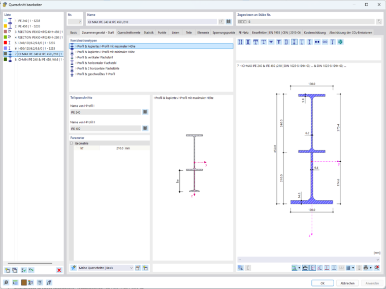
Variant 5.1: Distribution Type “Linear”, Welded Section, Cross-Section from RFEM 6
Variant 5.1 corresponds to Variant 4.2. The difference lies in the selection of cross-sections. Both cross-sections for the tapered member are defined as “Parametric – Thin-walled” cross-section type and “Welded” manufacturing type. The dimensions of the low cross-section (No. 5) correspond to an IPE 240, while the high cross-section (No. 6) is also modeled similarly to an IPE 240, but with a cross-section height of 450 mm.
The advantage of this variant is that the taper is not variable in either width or sheet thickness. Furthermore, unlike Variants 4.1 and 4.2, the height at the end of the taper can be reduced to 240 mm. However, the load capacity of this taper is lower than that of Variants 4.1 and 4.2 because the truncated section (actually an IPE 450) is formed using the thinner and narrower plates of an IPE 240.
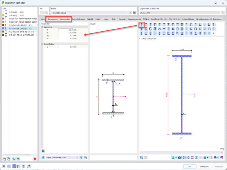
Variant 5.2: Distribution Type “Linear”, Welded Section, Cross-Section from RFEM 6
Variant 5.2 corresponds to Variant 5.1. An additional node No. 23 was inserted in the parallel-flange region. To the left of this node, the IPE 240 was used as a welded cross-section; to the right, the IPE 240 was used as a rolled cross-section. As a result, the transition from cross-sections with and without a rolling radius was shifted from the transition region of the taper to the parallel-flange region.
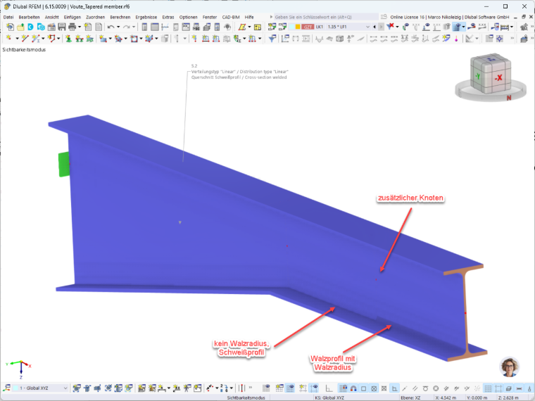
Summary and Evaluation
Various alternatives were shown, some of which are unsuitable for steel construction practice. Others underestimate the actual load capacity.
From a structural analysis perspective, a combination of Variant 2.1 for modeling and Variant 4.2 for the selection of cross-sections seems to be advantageous. This is demonstrated in Variant 6. However, an unavoidable step in the transition region between the taper and the parallel-flanged cross-section remains.
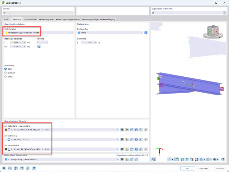
Another disadvantage is that, in this cross-section selection, the truncated part consists of a rolled section. In practice, the taper would likely be fabricated from plates.
To compensate for this disadvantage, the only option is to define the cross-sections using RSECTION 1. Here, the truncated section can be modeled as consisting of plates, with both the plate thicknesses adjusted to meet supply standards and the widths rounded to whole numbers. This is shown in Variant 7. Here is the image of the high cross-section No. 9:
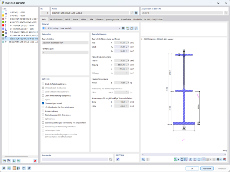
By clicking on the following image, you will be redirected to the Model to Download.