


This study verifies Steel Joints for RFEM by investigating the structural behaviour of bolted end-plate connections, both stiffened and unstiffened. The performance of these joints is evaluated against the design provisions of Eurocode 3 (EC-3) and validated through comparison with previously conducted experimental results.
Analytical Model
This study adopts the design criteria specified in EN 1993-1-8 for evaluating bolt resistance (shear and tension) and plate resistance (bearing and punching shear), utilizing the limit state formulations provided in Table 3.4.
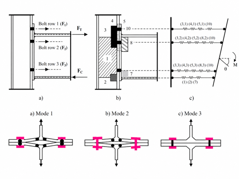
The design resistance of the equivalent T-stub is evaluated independently for the endplate and the column flange components. For each component, the governing design resistance, FT,Rd is defined as the minimum value derived from three potential failure mechanisms.
The individual resistance for each mode is calculated based on the plastic moment capacity of the flange (Mpl,1,Rd and Mpl,2,Rd) and the tension resistance of the bolt group (∑Ft,Rd). These modes account for complete flange yielding (Mode 1), bolt failure coupled with flange yielding (Mode 2), and pure bolt fracture (Mode 3).
Failure Modes:
The initial stiffness of the connection is given by the formula:
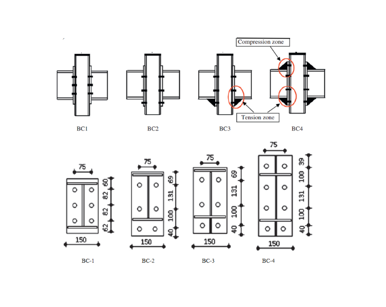
Geometric details of beam to column connection
In accordance with standard construction practice, all beam and column members were fabricated from S235 steel. The geometric configurations, including endplate and bolt-group arrangements, are illustrated in Figure 2, while the experimental test matrix and measured material properties are summarized in Table 1. As defined in the test matrix, Group A specimens (1BC-4BC) featured an HEA 120 column section paired with an IPE 240 beam section, with a uniform endplate thickness of 15 mm maintained across all specimens.
| Specimens | Column | Steel grade | Beam | Steel grade | Endplate Thickness, mm |
|---|---|---|---|---|---|
| BC1 | HEA120 | S235 | IPE240 | S235 | 15 |
| BC2 | HEA120 | S235 | IPE240 | S235 | 15 |
| BC3 | HEA120 | S235 | IPE240 | S235 | 15 |
| BC4 | HEA120 | S235 | IPE240 | S235 | 15 |
Discussion
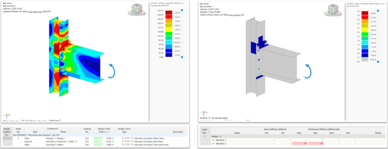
Steel Joints for RFEM Solution
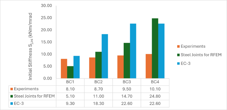
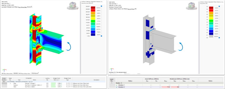
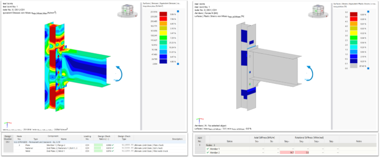
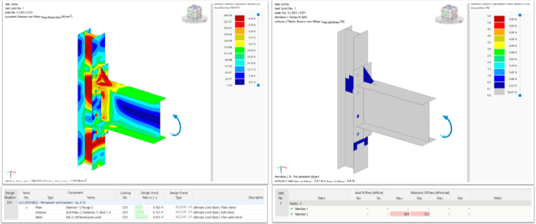
This study presents a combined experimental and numerical investigation into the structural performance of four end-plate beam-to-column connections, with particular emphasis on the behaviour of bolted end-plate joints with and without stiffeners. The experimental programme was complemented by dedicated T-stub component tests and detailed finite element (FE) modelling. Connection design was carried out using the Steel Joints add-on for RFEM 6, fully integrated within the global structural model. The FE models were validated against the experimental measurements and verified against the Eurocode 3 (EC-3) design provisions, then used to examine the localized deformation behaviour in detail. Figures 3 and 4, together with Tables 2 and 3, compare the moment resistance and rotational stiffness obtained from the experiments, the Steel Joints for RFEM 6 predictions, and the EC-3 analytical calculations.

| Specimens | Experiments | Steel Joints for RFEM | EC-3 | EC-3/RFEM |
|---|---|---|---|---|
| BC1 | 34.00 | 24.02 | 18.00 | 0.75 |
| BC2 | 47.00 | 34.51 | 33.00 | 0.96 |
| BC3 | 53.00 | 34.36 | 33.00 | 0.96 |
| BC4 | 65.00 | 39.15 | 33.00 | 0.84 |
| Specimens | Experiments | Steel Joints for RFEM | EC-3 |
|---|---|---|---|
| BC1 | 8.10 | 5.10 | 9.30 |
| BC2 | 8.70 | 11.00 | 18.30 |
| BC3 | 9.50 | 14.70 | 22.60 |
| BC4 | 10.10 | 24.80 | 22.60 |
Conclusions
The comparison shows RFEM tracks the experimental behaviour more closely than EC-3 for both moment resistance and initial stiffness. EC-3 underestimates capacity more severely and plateaus at 33.00 kNm across BC2-BC4 despite a 40% rise in measured capacity, indicating its prediction is governed by a single limiting component check insensitive to the varied parameters. For initial stiffness, RFEM shows a lower average deviation from experiment (0.66) than EC-3 (0.97) and is the only method that continues tracking the increasing stiffness trend through BC3-BC4 rather than plateauing. RFEM's over-prediction of stiffness at higher values is consistent with the general tendency of component-based models toward idealised component rigidity, and EC-3 shows comparable or larger over-prediction at BC2-BC3.
Overall, RFEM is the more reliable of the two tools for capturing joint strength and stiffness trends and is recommended as the primary verification method, with EC-3 retained as an independent check.
References
- Eurocode 3. Design of steel structures part 1-8: design of joints. European Standard EN 1993-1-8. European committee for standardization, Brussels, Belgium; 1993.
- Abidelah, Anis & Bouchair, Abdelhamid & Kerdal, Djamel. (2012). Experimental and analytical behaviour of bolted end-plate connections with or without stiffeners. Journal of Constructional Steel Research.