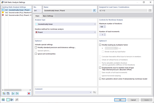
This feature helps you with the load application. You can have the required loading applied incrementally. This option is particularly suitable for your calculations according to the large deformation analysis. Furthermore, you can easily perform post‑critical analyses in RFEM.
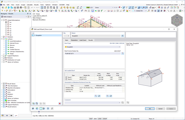
Do you want your structures to remain upright even in wind and snow? Then rely on the load wizards for plate and frame structures. You can now generate wind loads according to EN 1991‑1‑4 and snow loads according to EN 1991‑1‑3 (as well as other international standards). The load cases are generated depending on the roof shape.

Wind loads are also not a problem in your design. You can automatically generate wind loads as member loads or area loads (RFEM) on the following structural components:
- Vertical walls
- Flat roofs
- Monopitch roofs
- Duopitch/troughed roofs
- Vertical walls with duopitch roof
- Vertical walls with flat/monopitch roof
The following standards are available to you:
-
 EN 1991-1-4 (including National Annexes)
 -
 ASCE 7
 -
 CTE DB-SE-AE
 -
 GB 50009
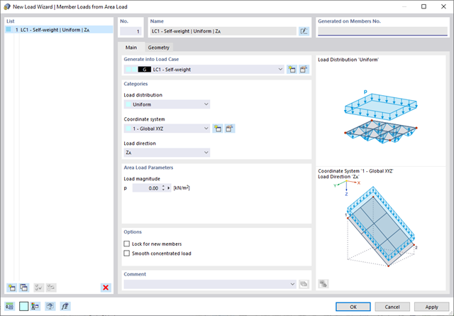
Use all types of loads without any difficulty. You can automatically convert the area loads into member loads or line loads (RFEM).
In the case of member loads from area loads, you have to define a plane via corner nodes or select cells in the graphic. Then the rest works by itself.
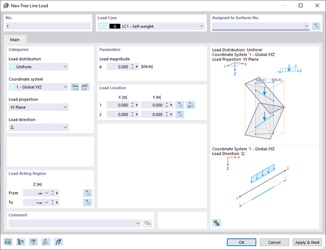
Also for pure member models, such as girder grillages, there is a useful feature for you. Here you can define free line loads (for example, from conveyor belts) and transfer them proportionally to members.
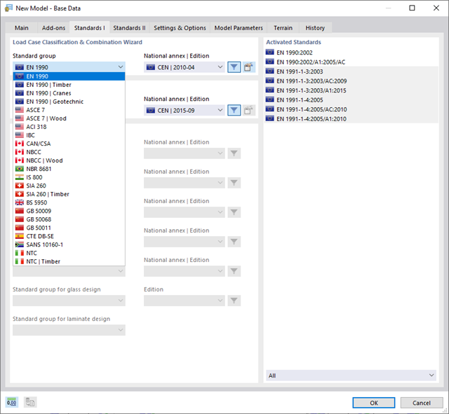
With Dlubal, you can safely and easily design structures all over the world. Select from a large number of standards in the Base Data. You can also decide whether to create the combinations automatically.
The following standards are available:
-
EN 1990
-
EN 1990 | Timber
-
EN 1990 | Road Bridges
-
EN 1990 | Cranes
-
EN 1990 | Geotechnical Engineering
-
EN 1990 | Base + Timber
-
EN 15512
-
ASCE 7
-
ASCE 7 | Timber
-
ACI 318
-
IBC
-
 CAN/CSA
 -
NBC
-
NBC | Timber
-
 NBR 8681
 -
 IS 800
 -
 SIA 260
 -
SIA 260 | Timber
-
 BS 5950
 -
GB 50009
-
GB 50068
-
GB 50011
-
CTE DB-SE
-
 SANS 10160-1
 -
 NTC
NTC -
NTC | Timber
-
 AS/NZS 1170.0
 -
 SP 20.13330:2016
 -
 TSC | Steel
For the European standards (EC), the following National Annexes are available:
-
 DIN | 2012-08 (Germany)
 -
CEN | 2010-04 (European Union)
-
 BDS | 2013-03 (Bulgaria)
 -
BS | 2009-06 (United Kingdom)
-
 CSN | 2015-05 (Czech Republic)
 -
 CYS | 2010-06 (Cyprus)
 -
 DK | 2013-09 (Denmark)
 -
 ELOT | 2009-01 (Greece)
 -
 EVS-EN 1990:2002+NA:2002 (Estonia)
 -
 IS | 2010-04 (Ireland)
 -
 LST | 2012-01 (Lithuania)
 -
 LU | 2020-03 (Luxembourg)
 -
 LVS | 2015-01 (Latvia)
 -
 MS | 2010-02 (Malaysia)
 -
 NBN | 2015-05 (Belgium)
 -
 NEN | 2011-12 (Netherlands)
 -
 NF | 2011-12 (France)
 -
 NP | 2009-12 (Portugal)
 -
 NS | 2016-05 (Norway)
 -
 ÖNORM | 2013-03 (Austria)
 -
 PN | 2010-09 (Poland)
 -
 SFS | 2010-09 (Finland)
 -
 SIST | 2010-08 (Slovenia)
 -
 SR | 2006-10 (Romania)
 -
 SS | 2008-06 (Singapore)
 -
 SS | 2019-01 (Sweden)
 -
 STN | 2010-01 (Slovakia)
 -
 TKP | 2011-11 (Belarus)
 -
UNE | 2010-07 (Spain)
-
 UNI | 2010-10 (Italy)
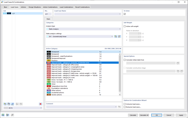
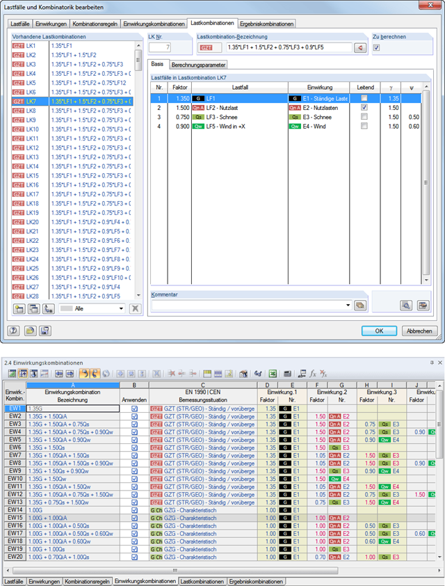
To ensure that your structures can cope with all loads, take a look at the "Load Cases and Combinations" dialog box. Here you can create and manage load cases. Furthermore, you can also generate action and load combinations as well as design situations here. You can assign the action categories of the selected standard to the individual load cases. If you have assigned several loads to an action category, they can act simultaneously or alternatively (for example, either wind from the left or wind from the right).
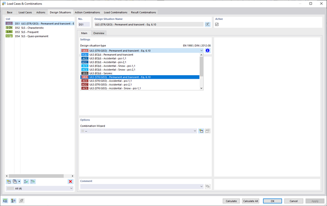
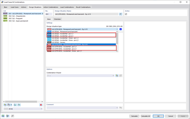
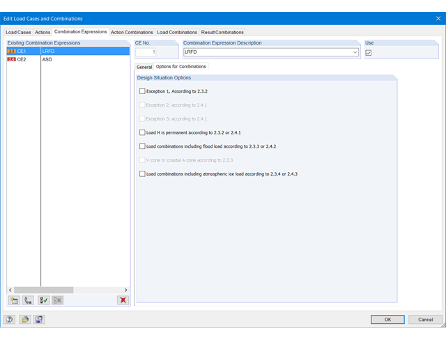
For the combination of actions, you have come to the right place. If you use them in the ultimate and the serviceability limit state, you can select various design situations according to the standard (for example, ULS (STR/GEO) - permanent/transient, SLS - quasi-permanent, and others). Optionally, you can also integrate imperfections in the combination and determine load cases that should not be combined with other load cases (for example, construction load for roof not combined with snow load).
Do your structures also have to withstand unusual conditions? Then select the "accidental" design situation. Here, accidental actions such as earthquake, explosion loads, collisions, and many others, are considered automatically. Furthermore, when using German standards, you can select the "Accidental - Snow" design situation to consider the "North German Plain" automatically as well.
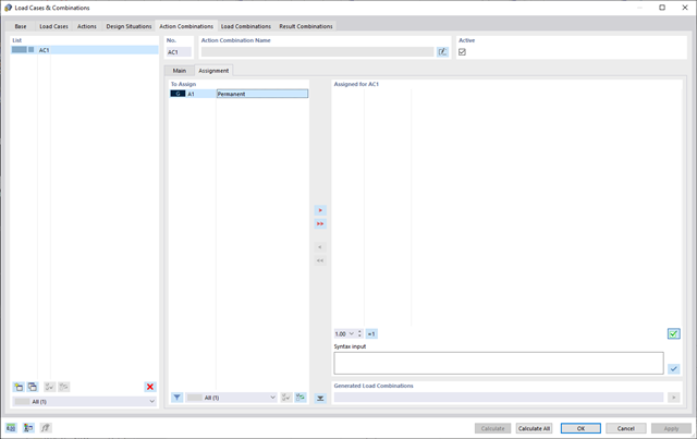
Do you want to combine actions? Then use this feature. Here, the actions are automatically superimposed in accordance with combination expressions and then displayed as "action combinations". You can define which action combinations will eventually be used for the generation of load or result combinations. Based on the created action combinations, you can estimate how the combination expressions affect the number of combinations.
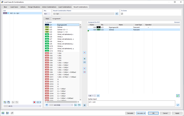
RFEM 6 offers you a wide range of helpful and efficient functions for working with load combinations. You can add the load cases included in load combinations together and then calculate them in consideration of the corresponding factors (partial safety and combination factors, coefficients regarding consequence classes, and so on). Generate the load combinations automatically in compliance with the combination expressions of the standard. You can perform the calculation according to the linear static analysis, second-order analysis, or large deformation analysis, as well as for post-critical analysis. Optionally, you can define whether the internal forces should be related to the deformed or non-deformed structure.
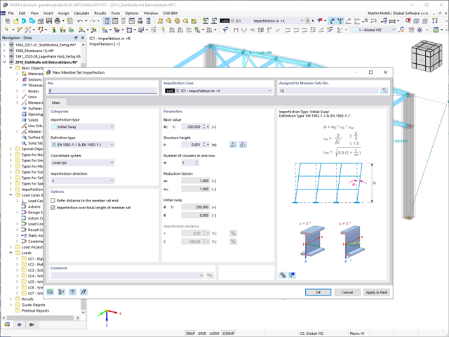
If you work with loads, find a selection of useful features here. Various load types are available to you for member and surface loads (force, moment, temperature, precamber, and so on). You can assign mmber loads to members, member sets, and member lists. In the case of imperfections, inclination and precamber can be determined precisely according to the Eurocode, the American standard ANSI/AISC 360, the Canadian standard CSA S16, and so on.
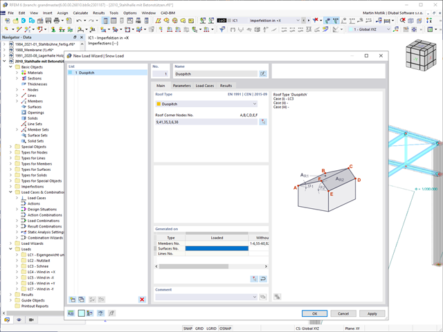
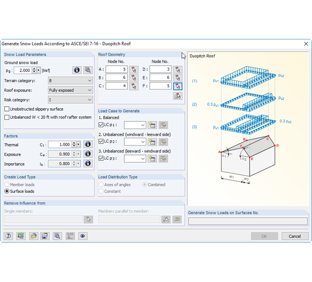
Do your structures also have to withstand snowfall? Use the Snow Load Wizard to generate snow loads as member loads or surface loads.
The following standards are available:
-
EN 1991-1-3 (incl. National Annexes)
-
ASCE 7
-
NBC
-
SIA 261
-
CTE DB-SE-AE
-
GB 50009
-
IS 875
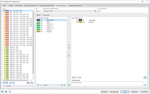
In the "Load Cases & Combinations" dialog box, you have an option to automatically generate load and result combinations as soon as you have selected the corresponding combination expressions. For example, you can also copy or add load cases in a clearly arranged window.
Furthermore, you can manage the load cases and combinations in the tables.
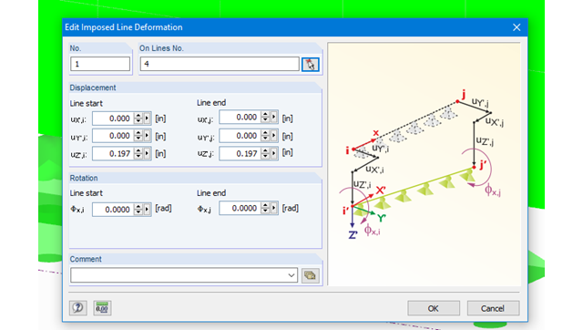
Imposed line deformations can be defined for supported lines in RFEM. For example, foundation settlements can be simulated with this function.
Moreover, it is possible to define imposed rotations for lines.
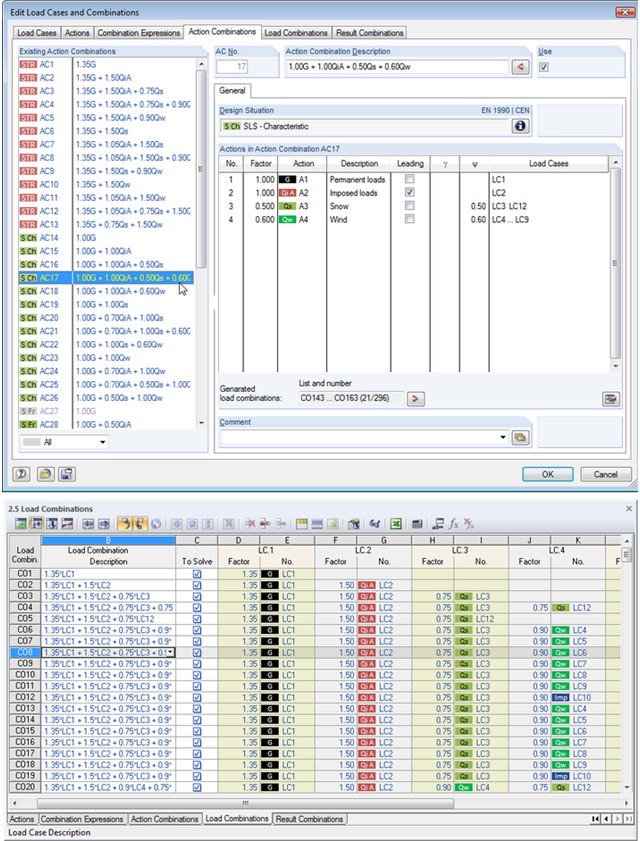
Utilize all the options of the 'Edit Load Cases and Combinations' dialog box to facilitate your work. Here you can automatically create load and result combinations after selecting the corresponding combination expressions. In this clearly arranged dialog box, you can also e.g. to copy, add, or renumber load cases.
Additionally, control the load cases and combinations in Tables 2.1 – 2.6.
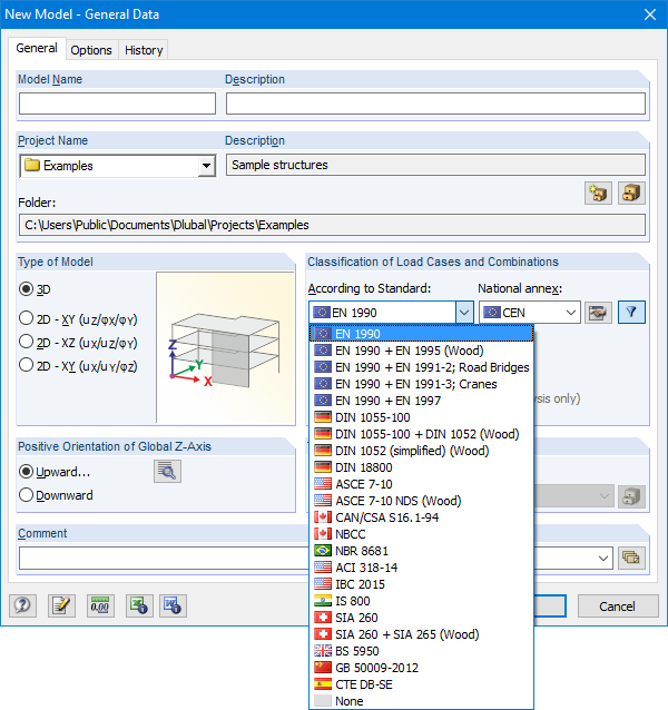
The Base Data dialog box includes a wide range of standards and the option to create combinations automatically. The following standards are available:
-
EN 1990:2002
-
EN 1990 + EN 1995:2004 (Timber)
-
EN 1990 + EN 1991-2; Road bridges
-
EN 1990 + EN 1991-3; Cranes
-
EN 1990 + EN 1997
-
to DIN 1055-100:2001-03
-
DIN 1055-100 + DIN 1052:2004-08 (timber)
-
DIN 1055-100 + DIN 18008 (Glass)
-
DIN 1052 (simplified) (timber)
-
DIN 18800:1990
-
ASCE 7‑10
-
ASCE 7-10 NDS (Wood)
-
ACI 318-14
-
IBC 2015
-
CAN/CSA S 16.1-94:1994
-
NBCC: 2005
-
NBR 8681
-
IS 800:2007
-
SIA 260:2003
-
SIA 260 + SIA 265:2003 (timber)
-
BS 5950-1:2000
-
GB 50009-2012
-
CTE DB-SE
For the European standards (EC), the following National Annexes are available:
-
DIN EN 1990/NA:2009-05 (Germany)
-
NBN EN 1990 - ANB: 2005 (Belgium)
-
BDS EN 1990:2003/NA:2008 (Bulgaria)
-
DK EN 1990/NA:2007-07 (Denmark)
-
SFS EN 1990/NA:2005 (Finland)
-
NF EN 1990/NA:2005/12 (France)
-
ELOT EN 1990:2009 (Greece)
-
UNI EN 1990/NA:2007-07 (Italy)
-
IS EN 1990:2002 + NA:2010 (Ireland)
-
LVS EN 1990:2003/NA:2010 (Latvia)
-
LST EN 1990/NA:2010-11 (Lithuania)
-
LU EN 1990/NA:2011-09 (Luxembourg)
-
MS EN 1990:2010 (Malaysia)
-
NEN EN 1990/NA:2006 (Netherlands)
- NS EN 1990/NA:2008 (Norway)
-
ÖNORM EN 1990:2007-02 (Austria)
-
NP EN 1990:2009 (Portugal)
-
PN EN 1990/NA:2004 (Poland)
-
SR EN 1990/NA:2006-10 (Romania)
-
SIST EN 1990: 2004/A1:2005 (Slovenia)
-
SS EN 1990:2008 (Singapore)
-
SS EN 1990/BFS 2010:28 (Sweden)
-
STN EN 1990/NA:2009-08 (Slovakia)
-
UNE EN 1990 2003 (Spain)
-
CSN EN 1990/NA:2004-03 (Czech Republic)
-
BS EN 1990/NA:2004-12 (the United Kingdom)
-
TKP EN 1990/NA:2011 (Belarus)
-
CYS EN 1990:2002 (Cyprus)
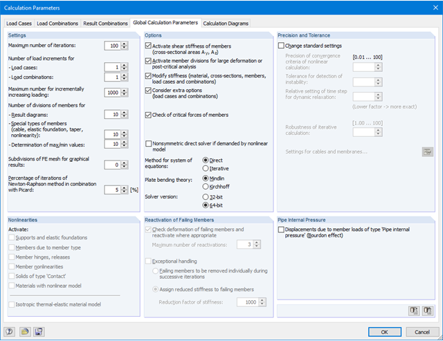
The loading can be applied incrementally. The increment option is especially useful for calculations according to the large deformation analysis. For members, you can consider shear deformations and apply internal forces to a deformed or undeformed structural system. In addition, RFEM allows you to perform post‑critical analyses.
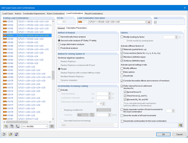
The load cases included in load combinations are added together and then calculated in consideration of the corresponding factors (partial safety and combination factors, coefficients regarding consequence classes, and so on). The load combinations can be created automatically in compliance with the combination expressions of the standard. The calculation can be performed according to the geometrically linear, second-order, or large deformation or as per the post-critical analysis. Optionally, you can define whether the internal forces should be related to the deformed or non-deformed structure.
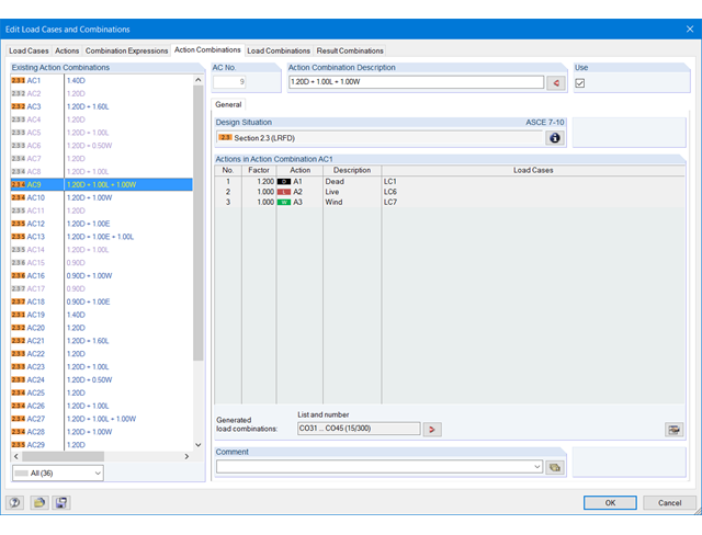
The actions are automatically superimposed in accordance with combination expressions and then displayed as "action combinations". It is possible to define which action combinations will eventually be used for the generation of load or result combinations. Based on the created action combinations, you can estimate how the combination expressions affect the number of combinations.
There are three options to reduce the number of combinations. The first two procedures are only available for the generation of load combinations, not for result combinations.
The first option allows for automatic analysis of all load case results (internal forces, deformations, and so on) of selected elements. Then, the program will generate only those combinations that include the load cases producing a maximum or minimum. In addition, you can define a maximum number of relevant load cases, or neglect load cases with a very small contribution to the maximum and minimum values.
The second option allows for automatic evaluation of generated temporary or user-defined result combinations. Then, only the governing load combinations are created.
The third option to reduce the number of generated combinations is to classify only selected actions as leading actions.
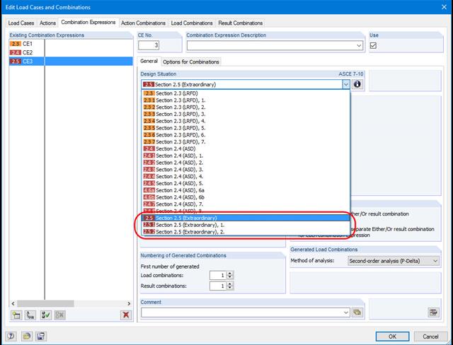
When you select the design situation 'Accidental', accidental actions such as earthquake, explosion loads, collisions, and others are automatically taken into account. When applying German standards, you can automatically consider the 'North German Plain' by selecting the design situation 'Accidental - Snow'.
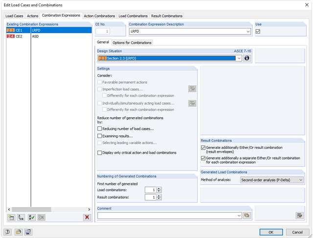
For the combination of actions in the ultimate and the serviceability limit state, you can select various design situations according to the standard (for example, ULS (STR/GEO) - permanent/transient, SLS - quasi-permanent, and others).
Furthermore, there is the option to integrate imperfections in the combination and to determine load cases that should not be combined with other load cases (for example, construction load for roof not combined with snow load).
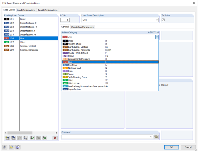
In the "Edit Load Cases and Combinations" dialog box, you can create and edit load cases as well as generate action, load, and result combinations. It is possible to assign various action types to the individual load cases in accordance with the selected standard. If several loads have been assigned to one action type, they can act simultaneously or alternatively (for example, wind from the left or right).
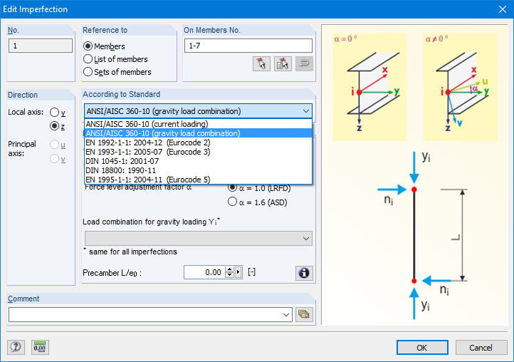
There are various load types available for member and surface loads (force, moment, temperature, precamber, and so on). Member loads can be assigned to members, member sets, and member lists. In the case of imperfections, inclination and precamber can be determined according to Eurocode or the American standard ANSI/AISC 360.
There are load generators available for beam structures, creating snow loads according to ASCE/SEI 7-10. The load cases are generated depending on the roof shape. Another generator creates coating loads (ice). You can save recurring load combinations as templates.
After generating the loads, you can check the results in clearly arranged tables. The output includes all information about the generated load cases and loads due to self-weight, wind load, and ice load. All loads are itemized in structural objects and equipment.
In the 'Edit Load Cases and Combinations' dialog box, there is an option to automatically generate load and result combinations after selecting the corresponding combination expressions. In this clearly arranged dialog box, it is also possible to copy, add, or renumber load cases, for example.
Furthermore, you can manage the load cases and combinations in Tables 2.1 – 2.6.
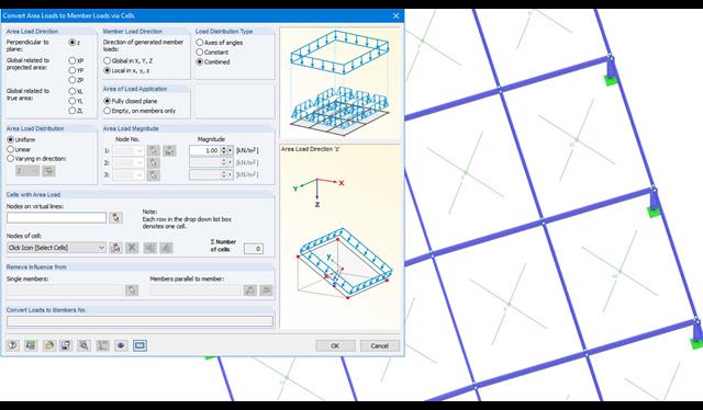
Area loads can be automatically converted into member or line loads. There are 3 options available for this:
- Generate Member Loads from Area Load via Plane
- Member loads from area loads via cells
- Line loads from surface loads on openings
In the case of member loads from area loads, a plane has to be defined via corner nodes or cells have to be selected in the graphic. The area load can either be applied to the entire surface or only the effective or projected surface of the members.
For the 'Line Loads from Area Loads on Openings' function, the corresponding openings are selected.
Online Manual RFEM | Member Loads from Area Loads via Plane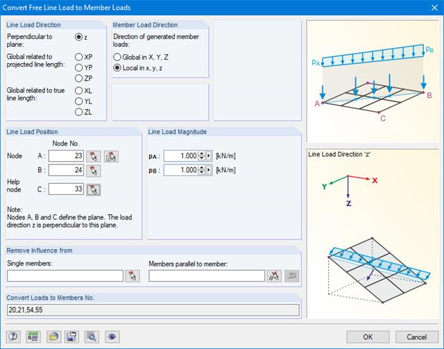
For pure member models such as grillages, you can define free line loads (e.g. from conveyor belts) and transfer them proportionally to members.
More Information