Pytanie:
Jak utworzyć połączenie nakładkowe w rozszerzeniu Połączenia stalowe?
Odpowiedź:
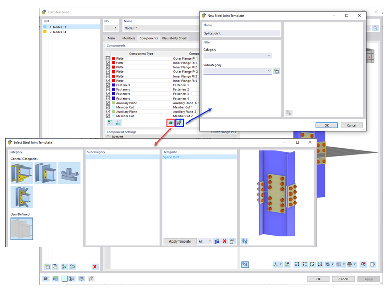
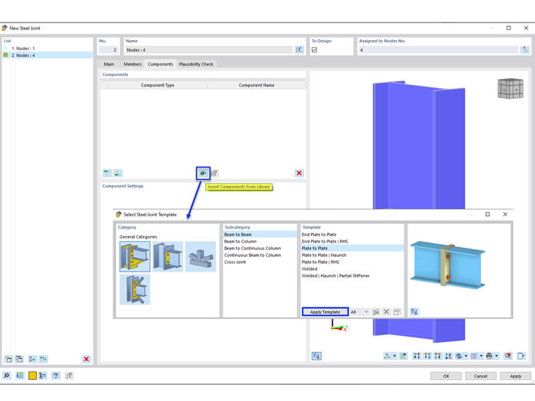
Za pomocą szablonu „Płyta-płyta” z biblioteki Komponenty (rysunek 01) można za pomocą blach czołowych w prosty sposób utworzyć połączenie nakładkowe.
W przypadku połączenia nakładkowego bez blach czołowych konfigurację można utworzyć ręcznie, dodając poszczególne komponenty (rysunek 02).
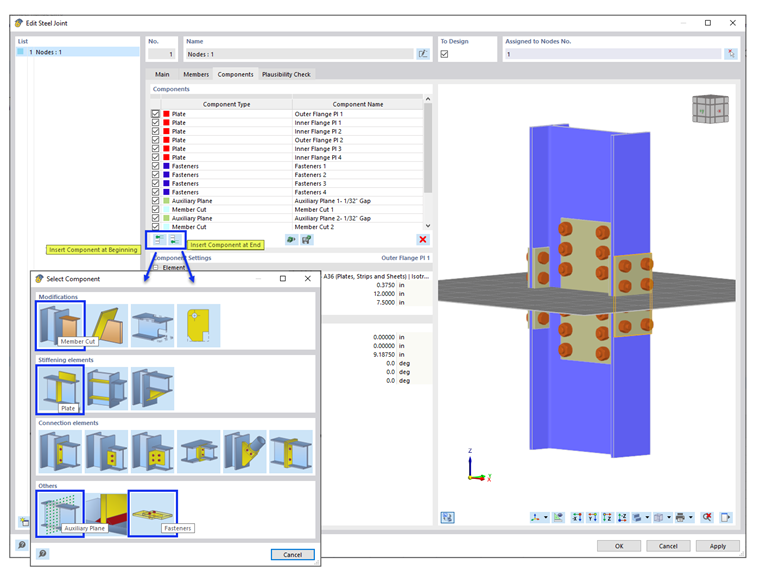
Konfiguracja obejmuje następujące komponenty. Każdy komponent można łatwo usunąć lub skopiować, klikając w niego prawym przyciskiem myszy.
- Plates (2 outer flange plates, 4 inner flange plates, 2 web plates)
- Fasteners (4 sets to connect 4 inner flange plates, 1 set to connect web plate)
- Auxiliary Plane (2 planes)
- Member Cut (2 cuts) with the type of cut ‘By auxiliary plane’)
It is required that a small gap is created using “Member Cut” and “Auxiliary Plane”. The gap is divided between the two members (i.e., 1/16” gap is applied as 1/32” displacement to each member).
Alternatively, a sample model “AISC Splice Connection” can be downloaded and saved as a user-defined template (Image 03).