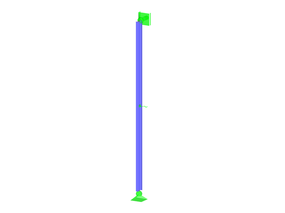
Stabilized Buckling Member
Model to Download
Description
If a member is laterally supported due to a compressive axial force to prevent buckling, it must be ensured that the lateral support is actually able to prevent buckling. Therefore, the aim of this article is to determine the ideal spring stiffness of a lateral support using the winter model.
Model Used in
Keywords
Ideal Spring stiffness Lateral Support Buckling member
Links
Write Comment...
Write Comment...
Disclaimer

New
Determination of Ideal Spring Stiffness for Lateral Supports of Buckling Members
If a member is laterally supported to prevent buckling due to a compressive axial force, it must be ensured that the lateral support is actually able to prevent buckling.

SHAPE-THIN determines the effective cross-sections according to EN 1993-1-3 and EN 1993-1-5 for cold-formed sections. You can optionally check the geometric conditions for the applicability of the standard specified in EN 1993‑1‑3, Section 5.2.
The effects of local plate buckling are considered according to the method of reduced widths and the possible buckling of stiffeners (instability) is considered for stiffened sections according to EN 1993-1-3, Section 5.5.
As an option, you can perform an iterative calculation to optimize the effective cross-section.
You can display the effective cross-sections graphically.
Read more about designing cold-formed sections with SHAPE-THIN and RF-/STEEL Cold-Formed Sections in this technical article: Design of a Thin-Walled, Cold-Formed C-Section According to EN 1993-1-3.
- I am trying to manually check the deformations from the CRANEWAY add-on module. However, I obtain great deviations. How to explain the differences?
- What should be considered when using a failure of columns under tension in the RF‑/DYNAM Pro – Equivalent Loads add-on module?
- Why is there no stability analysis displayed in the results despite the activation of the stability analysis in RF‑/STEEL EC3?
- How can I model and design a crane runway girder with Dlubal Software?
- Is it possible to set user-defined values when viewing solid stress results?
- Why do I get large differences for the design of a longitudinally stiffened buckling panel in comparison with the German and Austrian National Annex?
- How are the signs for the release results of a line release and line hinges interpreted?
- How can I perform the stability analysis in RF‑/STEEL EC3 for a flat bar supported on edges, such as 100/5? Although the cross-section is rotated by 90° in RFEM/RSTAB, it is displayed as lying flat in RF‑/STEEL EC3.
- How can I create a curved or arched section?
- How is the rotational stiffness of a buckling stiffener determined in PLATE‑BUCKLING?