According to George Winter, the ideal spring stiffness is that which is at least necessary to completely prevent the lateral buckling of the main member with regard to its critical buckling load and to act accordingly as a full support. Winter speaks of "full bracing". According to this, the zero crossing of the buckling curve should be located at this support spring, so that the buckling curve itself has two or more waves instead of one.
In the Winter model, an ideally straight compression member with pinned ends on both sides is considered, which is restrained in the middle by a support spring. To determine the ideal spring stiffness, Winter developed the idealized model shown in Image 01.
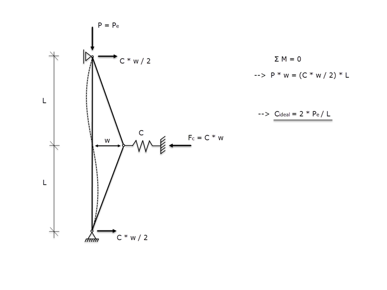
The notional release is based on the assumption of an inflection point in the flexural buckling curve, if the span lengths are the same. If the critical buckling load Pe is applied as compression axial force and the member is displaced by the dimension w in the support spring's region, we obtain the ideal spring stiffness Cideal, after clearing the zone around the notional release by imaginary cuts and setting up conditions for the moment equilibrium.
|
Cideal |
Ideal spring stiffness |
|
Pe |
Critical load |
|
L |
Span between the support and the support spring |
This correlation between spring stiffness and critical buckling load results in the function shown in Image 02. Thus, a buckling shape with lateral displacement in the support spring's region occurs for spring stiffnesses smaller than Cideal.
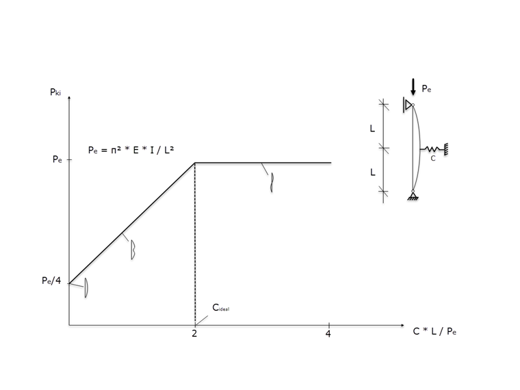
The critical load Pe can be determined with the add-on modules RSBUCK and RF-STABILITY, or manually, as follows.
|
Pe |
Critical load |
|
E |
Modulus of elasticity |
|
I |
Second moment of area |
|
L |
Span between the support and the support spring |
Determination of Ideal Spring Stiffness Using Example
In the model (Image 03), a compression member (IPE 400) with pinned ends and the parameters E = 21,000 kN/cm², Iz = 1,318 cm4 and L = 5 m is restrained in the middle by a support spring.
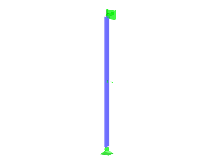
This results in a critical load Pe of 1,089 kN, which results in an ideal spring stiffness Cideal for the support spring defined in the member's center of 436 kN/m.
Determination of Stabilizing Force in Support Spring Using Example of Buckling Member with Imperfection
After performing ultimate load tests on buckling columns in addition to the theoretical considerations mentioned above, we ascertained that the theoretically ideal spring stiffness is insufficient for columns with geometric imperfections.
Accordingly, deformation w from Image 01 is supplemented by predeformation w0 to wtot.
wtot = w + w0
After setting up the moment equilibrium around the notional hinge (Image 01), the result is:
P ⋅ (w + w0) = C ⋅ w ⋅ L / 2
This results in:
|
wges |
Gesamtverformung aus Knickauslenkung und Vorkrümmung |
|
w0 |
Vorverformung aus Vorkrümmung aufgrund geometrischer Imperfektion |
|
P |
Vorhandene Drucknormalkraft im Knickstab |
|
C |
Federsteifigkeit der seitlichen Stützfeder |
|
L |
Stützweite zwischen Auflager und Stützfeder |
And for Cideal = 2 ⋅ Pe / L:
|
wges |
Gesamtverformung aus Knickauslenkung und Vorkrümmung |
|
w0 |
Vorverformung aus Vorkrümmung aufgrund geometrischer Imperfektion |
|
P |
Vorhandene Drucknormalkraft im Knickstab |
|
Pe |
Verzweigungslast im Knickstab |
Based on these equations, the stabilizing force Fc results in:
|
Fc |
Lateral stabilizing force |
|
C |
Spring stiffness of the lateral support |
|
w |
Lateral deflection of the buckling member in the center |
|
P |
Compression axial force in the buckling member |
|
L |
Span between the support and the support spring |
|
w0 |
Pre-deformation from precamber due to geometric imperfection |
|
Pe |
Critical load of the buckling member |
The stabilizing force Fc can thus be determined from the following parameters:
- Existing compressive force P = 500 kN
- Span between the support and the support spring L = 5 m
- Precamber from imperfection w0 = Ltotal / 300 = 10 / 300 = 0.0333 m
Critical load Pe = 1,089 kN
This results in a stabilizing load Fc = 12.3 kN. RFEM determines 11.7 kN.
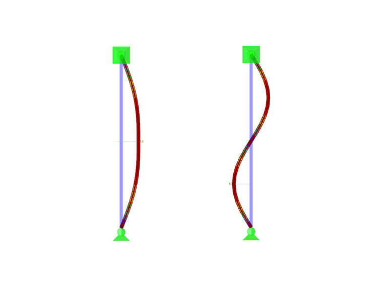
Conclusion
To check the correctness of the determined spring stiffness, you can look at the results from RF-STABILITY. The first mode shape is a double-wave buckling curve with zero crossing at the support spring level, while the second shape is a single-wave buckling curve supported by the support spring (Image 04). Both have approximately the same critical buckling load.