


Frame Joints of Frames According to EN 1993-1-8 (EC 3)

RF-/FRAME-JOINT Pro | Features
- Design of knee joints, T-joints, cross joints, and continuous column connections with I-shaped sections
- Import of geometry and load data from RFEM/RSTAB or manual specification of the connection (for example, for recalculation without an existing RFEM/RSTAB model)
- Flush top connections or connections with bolt row in extension
- Design of positive and negative frame joint moments
- Various inclinations of right and left horizontal beams as well as application to frames of duopitch and monopitch roofs
- Consideration of additional flanges in a horizontal beam, for example for tapered sections
- Symmetrical and asymmetrical T-joints or cross joints
- Two-sided connection with different cross-section depth on the right and left
- Automatic preliminary design of bolt layout and required stiffening
- Optional design mode with possibility to specify all bolt spacing, welds, and sheet thicknesses
- Screwability check with adjustable dimensions of used wrenches
- Connection classification by stiffness and calculation of the spring stiffness of connections considered in the internal forces determination
- Check up to 45 individual designs (components) of the connection
- Automatic determination of governing internal forces for each individual design
- Controllable connection graphics in rendering mode with specifications of material, sheet thickness, welds, bolt spacing, and all dimensions for construction
- Integrated and flexibly extensible settings of National Annexes according to EN 1993-1-8 standard
- Automatic conversion of internal forces from structural analysis into respective sections, also for eccentric member connections
- Automatic determination of initial stiffness Sj,ini of the connection
- Detailed plausibility check of all dimensions, including specifications of input limits (for example, for edge distances and hole spacing)
- Optional application of compression forces to a column through contact
- Possibility to update the cross-section depth of horizontal beams in case of tapered connections after connection geometry optimization in RF-/FRAME-JOINT Pro

RF-/FRAME-JOINT Pro | Input
The RF-/FRAME-JOINT Pro add-on module designs connections of structures calculated in RFEM/RSTAB. If there is no RFEM/RSTAB structure available, you can define the geometry and loading manually; for example, when checking external calculations, for example.
Designed nodes are usually imported from RFEM/RSTAB. The module recognizes all connected members automatically and assigns a connection type to them. Depending on the connection type, you can define further details of ribs, backing plates, web plates, bolts, welds, and hole spacing. As loads, you can select any load case, load combination or result combination in RFEM/RSTAB.
In the case of the "preliminary design" calculation mode, RF-/FRAME-JOINT Pro performs the first calculation step to suggest applicable layouts. After you select the relevant layout, the module displays all designs in detailed result tables and various graphics.

RF-/FRAME-JOINT Pro | Structural Analysis
The RF-/FRAME-JOINT Pro add-on module performs the following designs according to the standards EN 1993-1-8 or DIN 18800:
- Beam end plate and column flange according to the plastic hinge theory
- Tension of bolts (including contact forces)
- Shearing of bolts
- Tension force introduction in column web and beam web
- Buckling analysis of gusset plate
- Shear design of gusset plate
- Compression force introduction in column web and buckling design of web plate
- If required:
- Design of diagonal stiffeners
- Web stiffener
- Supplementary web plates
- Compression force introduction in horizontal beam
- Design of welds

RF-/FRAME-JOINT Pro | Results
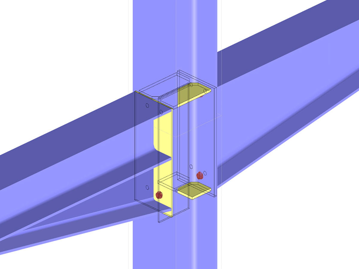
First, the module combines governing designs of the column and the horizontal beam and displays the connection geometry in a result table. The other result tables include all important design details such as flow line lengths, load-bearing capacity of screws, weld stresses, or connection stiffnesses. All connections are visualized in a 3D rendering graphic.
Dimensions, material specifications, and welds that are important for the construction of the connection are visible immediately and can be printed out. It is possible to visualize the connections in RF-/FRAME-JOINT Pro or directly in the RFEM/RSTAB model. All graphics can be included in the RFEM/RSTAB printout report or printed directly. Due to the scaled output, an optimal visual check is possible as early as in the design phase.


.png?mw=200&hash=ceabdac71454991b172d1a40faa3844b9a756ff1)
Calculate Your Price
.jpg?mw=400&hash=8ec1c00dfd4e646025627a5a9e3c865accc94aab)


