


Question:
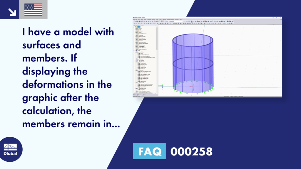
I have a model with surfaces and members. When displaying the deformations in the graphic after the calculation, the members remain in their original positions.
However, the members are connected to the surfaces, and the member deformations are also displayed in the table. Why?
Answer:
In order to avoid a confusing display, the member deformations are only displayed as lines in the default setting.
In Project Navigator - Display, you can adjust the display so the member deformations are also displayed as rendered cross-sections (Image 01).
Furthermore, it is possible to hide the undeformed model in the "Display" navigator in order to consider only the deformations (Image 02).