We provide hints and tips to help you get started with the basic program RFEM.
Home Support & Learning Learning Videos FAQ 003262 | What is the easiest way to define a polygonal surface graphically?
FAQ 003262 | What is the easiest way to define a polygonal surface graphically?
Video
First Steps with RFEM
Question
What is the easiest way to define a polygonal surface graphically?Answer
Basically there are two options:
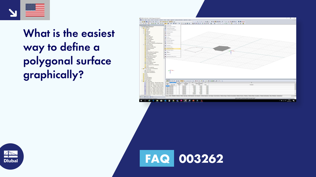
- If no structural lines are defined yet, a polygonal surface can be defined by menu bar → "Insert" → "Model Data" → "Surfaces" → "Plane" → "Graphically" → "Polygon", see picture 1
- If structural lines are already defined, a polygonal surface can be defined by menu bar → "Insert" → "Model Data" → "Surfaces" → "Plane" → "Graphically" → "Select Boundary Lines", see picture 2
Keywords
Dlubal FAQ Surface Polygonal Graphically Frequently Asked Question FAQ about Dlubal Question and Answer about Dlubal
Links
Contact us
Do you have any questions about our products or need advice on selecting the products needed for your projects?
Contact us via our free e-mail, chat, or forum support or find various suggested solutions and useful tips on our FAQ page.
Recommended Events
Eurocode 5 | Timber structures according to EN 1995-1-1
Online Training 03/17/2021 8:30 AM - 12:30 PM CET
Eurocode 3 | Steel structures according to DIN EN 1993-1-1
Online Training 03/18/2021 8:30 AM - 12:30 PM CET
Eurocode 3 | Steel structures according to DIN EN 1993-1-1
Online Training 05/06/2021 8:30 AM - 12:30 PM
Eurocode 2 | Concrete structures according to DIN EN 1992-1-1
Online Training 05/11/2021 8:30 AM - 12:30 PM
Eurocode 5 | Timber structures according to DIN EN 1995-1-1
Online Training 05/20/2021 8:30 AM - 12:30 PM
RFEM | Structural dynamics and earthquake design according to EC 8
Online Training 06/02/2021 8:30 AM - 12:30 PM
Videos
Models to Download
Knowledge Base Articles

New
The ‘Mapped FE Mesh Preferred’ option has an influence on the mesh generation of surfaces with curved and folded outlines.
Screenshots
Product Features Articles
New
Increased Calculation Performance by Reducing the Nodal Degrees of Freedom
The number of degrees of freedom in a node is no longer a global calculation parameter in RFEM (6 degrees of freedom for each mesh node in 3D models, 7 degrees of freedom for the warping torsion analysis). Thus, each node is generally considered with a different number of degrees of freedom, which leads to a variable number of equations in the calculation.
This modification speeds up the calculation, especially for models where a significant reduction of the system could be achieved (e.g. trusses and membrane structures).
Frequently Asked Questions (FAQ)
- Why does the vertical position of a result member in my model have no influence on the bending moment My of the member?
- Can I keep the results from RWIND Simulation when deleting the FE mesh if I only adjust materials or support conditions?
- How do I model a tent roof with two cone tips?
- How can I change the colors of the selection and preselection?
- How can I create a curved or arched section?
- How are the signs for the release results of a line release and line hinges interpreted?
- Is it possible to make the generated member loads from area loads via plane to act eccentrically on the member cross-section?
- After the calculation in the RF‑/DYNAM Pro - Equivalent Loads add-on module, the size of my file has increased significantly. The performance has worsened enormously. What could be the reason for this?
- Why are my imperfections displayed graphically in different ways and can I adjust the display?
- What happens with the programs and add-on modules in the case of the timeout of a network license? And how can I increase the timeout?
Customer Projects