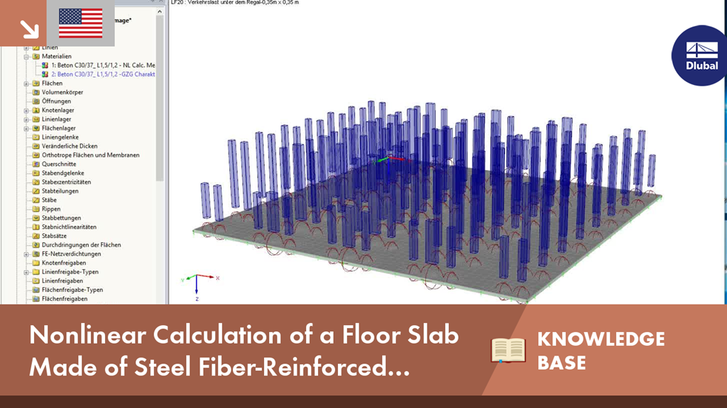
We provide hints and tips to help you get started with the basic program RFEM.
Home Support & Learning Learning Videos KB 001623 | Nonlinear Calculation of a Floor Slab Made of Steel Fiber Reinforced Concrete in the Ultimate Limit State with RFEM
KB 001623 | Nonlinear Calculation of a Floor Slab Made of Steel Fiber Reinforced Concrete in the Ultimate Limit State with RFEM
Video
First Steps with RFEM
Description
Steel fiber reinforced concrete is nowadays mainly used for industrial floors or hall floors, for foundation plates with low loads, basement walls and basement floors. Since the publication of the first guideline by the German Committee for Reinforced Concrete (DAfStb) about steel fiber reinforced concrete in 2010, the structural engineer can use standards for the design of the composite material steel fiber reinforced concrete, which makes the use of fiber reinforced concrete increasingly popular in construction. This article describes the nonlinear calculation of a foundation plate made of steel fiber reinforced concrete in the ultimate limit state with the FEA software RFEM.
Keywords
Dlubal Knowledge Base Steel fiber reinforced concrete Foundation plate Floor slab High-bay warehouse Industrial floor Fiber reinforced concrete Post-cracking tensile strength Performance class Dlubal KB Knowledge Base Technical contribution to Dlubal Software
Links
Contact us
Do you have any questions about our products or need advice on selecting the products needed for your projects?
Contact us via our free e-mail, chat, or forum support or find various suggested solutions and useful tips on our FAQ page.
Recommended Events
Eurocode 5 | Timber structures according to EN 1995-1-1
Online Training 03/17/2021 8:30 AM - 12:30 PM CET
Eurocode 3 | Steel structures according to DIN EN 1993-1-1
Online Training 03/18/2021 8:30 AM - 12:30 PM CET
Eurocode 3 | Steel structures according to DIN EN 1993-1-1
Online Training 05/06/2021 8:30 AM - 12:30 PM
Eurocode 2 | Concrete structures according to DIN EN 1992-1-1
Online Training 05/11/2021 8:30 AM - 12:30 PM
Eurocode 5 | Timber structures according to DIN EN 1995-1-1
Online Training 05/20/2021 8:30 AM - 12:30 PM
RFEM | Structural dynamics and earthquake design according to EC 8
Online Training 06/02/2021 8:30 AM - 12:30 PM
Videos
KB 000868 | General method for stability designs according to EN 1993-1-1 and buckling in the ...
Length 1:43 min
KB000610 | Automatically Dimensioning the Foundation Slab Geometry with RF-/FOUNDATION Pro
Length 0:40 min
KB 000674 | Defining Mandrel Diameter for Foundation Reinforcement in RF-/FOUNDATION Pro
Length 0:36 min
Models to Download
Knowledge Base Articles

New
General method for stability designs according to EN 1993-1-1 and buckling in the main bearing plane
In EN 1993-1-1, the General Method was introduced as a design format for stability designs, which can be used for planar systems with any boundary conditions and variable structural height.
Screenshots
Product Features Articles

Material Model Orthotropic Masonry 2D
The material model Orthotropic Masonry 2D is an elastoplastic model that additionally allows softening of the material, which can be different in the local x- and y-direction of a surface. The material model is suitable for (unreinforced) masonry walls with in-plane loads.
Frequently Asked Questions (FAQ)
- How are the signs for the release results of a line release and line hinges interpreted?
- How can I create a curved or arched section?
- Is it possible to manually specify a longitudinal reinforcement for design in RF‑PUNCH Pro?
- Can I simulate the cracked state of a concrete cross-section for a bending beam with the "Isotropic Nonlinear Elastic 1D" material model?
- Why is the deflection of the reinforced concrete floor sometimes greater when selecting a larger basic reinforcement?
- I have a question about the message No. 47 in RFEM. What is the exact meaning of the word "integrate"? What is the resulting effect?
- How can I view the depth of the concrete compression zone in RF‑/CONCRETE?
-
If I do not specify any basic reinforcement in RF‑CONCRETE Surfaces, I obtain the value X as an additionally required reinforcement. If I enter this value X as the provided basic reinforcement, I correctly do not get any additional required reinforcement.
However, if I enter a lower value than the determined required total reinforcement as the basic reinforcement, the additionally required reinforcement is increased in such a way that the originally required reinforcement content is exceeded. Why? - Why does the RF‑CONCRETE Surfaces add-on module not increase the amount of reinforcement until the SLS designs have a design ratio of 1.0?
- How can I get the member end forces to design the connections?
Customer Projects