FAQ 004942 EN-US
After the design with RF‑/TIMBER Pro, I optimized a cross-section. Why is the utilization of the optimized cross-section exceeded now?
Answer
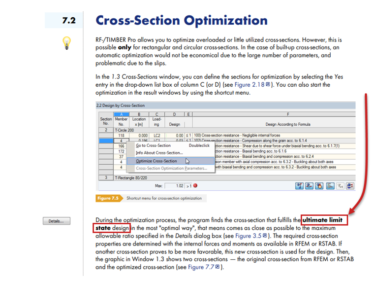
The optimization of cross-sections in RF‑/TIMBER Pro is based exclusively on the ultimate limit state (ULS), not the serviceability limit state (SLS), see the image from the RF‑TIMBER Pro manual.
More information about the cross-section optimization can be found in the RF-TIMBER Pro manual on pages 76-78 (also available with the F1 key in the add-on module).
Keywords
Cross-section optimization Optimization Cross-section Design ratio
Contact us
Did you find your question?
If not, contact us via our free e-mail, chat, or forum support, or send us your question via the online form.
Recommended Events
Timber Beam and Surface Structures | Part 1: Modeling, Load Input, Combinatorics
Webinar 05/04/2021 2:00 PM - 3:00 PM CEST
Eurocode 3 | Steel structures according to DIN EN 1993-1-1
Online Training 05/06/2021 8:30 AM - 12:30 PM CEST
Eurocode 5 | Timber structures according to DIN EN 1995-1-1
Online Training 05/20/2021 8:30 AM - 12:30 PM CEST
Membrane Structures with Wind Loads from CFD Wind Simulation
Webinar 03/24/2020 3:00 PM - 4:15 PM CET
Videos
Models to Download
Knowledge Base Articles

New
Filter option for the result tables in the design modules
When designing many members in one design case, it is sometimes difficult to recognize the governing designs. To improve the overview and to display the relevant designs in a compact way, you can use the filter options under the result tables. These are included in all design modules of steel, aluminum and timber structures in RFEM and RSTAB.
Screenshots
Product Features Articles

The cross-section resistance design analyzes tension and compression along the grain, bending, bending and tension/compression as well as the strength in shear due to shear force.
The design of structural components at risk of buckling or lateral-torsional buckling is performed according to the Equivalent Member Method and considers the systematic axial compression, bending with and without compressive force as well as bending and tension. Deflection of inner spans and cantilevers is compared to the maximal allowable deflection.
Separate design cases allow for a flexible and stability analysis of members, sets of members, and loads.
Design-relevant parameters such as the stability analysis type, member slendernesses, and limit deflections can be freely adjusted.
Frequently Asked Questions (FAQ)
- I can not calculate members with double rectangular cross-sections and linearly variable cross-section height in the HolzPro add-on module. What is the reason?
- In RF-/TIMBER AWC and RF-/TIMBER CSA, I receive the error that says torsion limit exceeded. How do I bypass this error message?
- Why is the strength always reduced by the kmod value of 0.6 during the calculation in the RF‑LAMINATE add‑on module, although I have load combinations with variable loads?
- Can I consider a reduction of the stiffness according to the German regulation NCI NA.5.9 in TIMBER Pro?
- I have selected all available members for design in RF-/TIMBER Pro. Why are tapered members not designed?
- When performing the fire resistance design with TIMBER Pro, I get the error 10001. How can I fix the error?
- Is it possible to set user-defined values when viewing solid stress results?
- How are the signs for the release results of a line release and line hinges interpreted?
- How can I create a curved or arched section?
- Is it possible to design the support pressure or the compression perpendicular to the grain in RX‑TIMBER?
Customer Projects