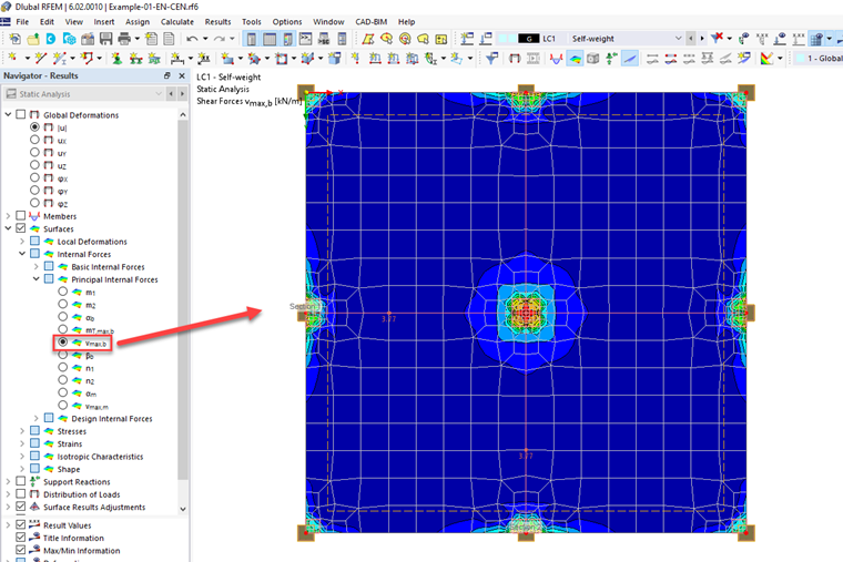
The value "VEd" from the concrete design does not exist in the static analysis.
However, you can display the result "vmax,b" from the main internal forces of the surface. The concrete design uses this "vmax,b" as "VEd".
The value "VEd" from the concrete design does not exist in the static analysis.
However, you can display the result "vmax,b" from the main internal forces of the surface. The concrete design uses this "vmax,b" as "VEd".
In the "Edit Section" dialog box, you can display the buckling shapes of the Finite Strip Method (FSM) as a 3D graphic.
The seismic design result is categorized into two sections: member requirements and connection requirements.
The "Seismic Requirements" include the Required Flexural Strength and the Required Shear Strength of the beam-to-column connection for moment frames. They are listed in the ‘Moment Frame Connection by Member’ tab. For braced frames, the Required Connection Tensile Strength and the Required Connection Compressive Strength of the brace are listed in the ‘Brace Connection by Member’ tab.
The program provides the performed design checks in tables. The design check details clearly display the formulas and references to the standard.
In the Concrete Design provides an option to perform seismic design according to AISC 341-16 for steel members.
Five SFRS types (Seismic Force-Resisting Systems) are available for this.