


The reduced stress method is implemented in PLATE-BUCKLING. This article provides some explanations that can be decisive for the design of stiffened buckling panels.
Determination of Buckling Values
Generally, there are two options for determining the buckling values of stiffened buckling panels. First, you can obtain the values directly from diagrams by using the existing boundary conditions in accordance with [2] and [3], or second, you can perform an eigenvalue calculation. The eigenvalue calculation determines the critical load factors for the respective existing stress. You then obtain the buckling values by recalculation using the critical buckling stress.
Selection of Governing Mode Shape
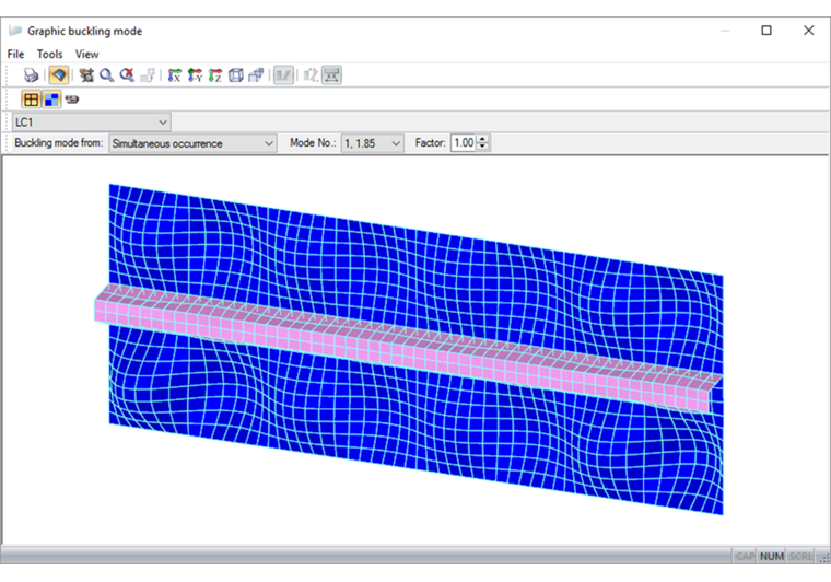
Evaluation of the determined mode shapes is essential for the design. The buckling analysis should be performed for the stiffened panel, and the corresponding buckling mode should show the global failure mode. The first determined mode shape is governing for the assessment of whether there is buckling of a subpanel, a panel section, or the entire stiffened plate. The following example shows the first mode shape for the subpanel buckling above and below the longitudinal stiffener.
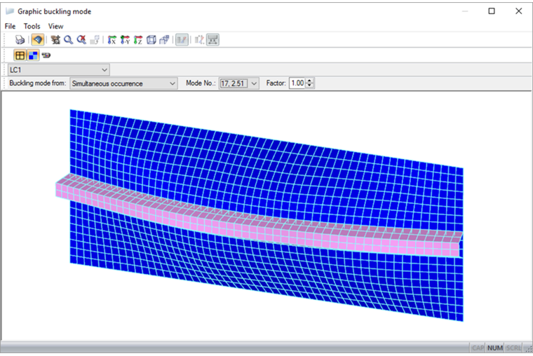
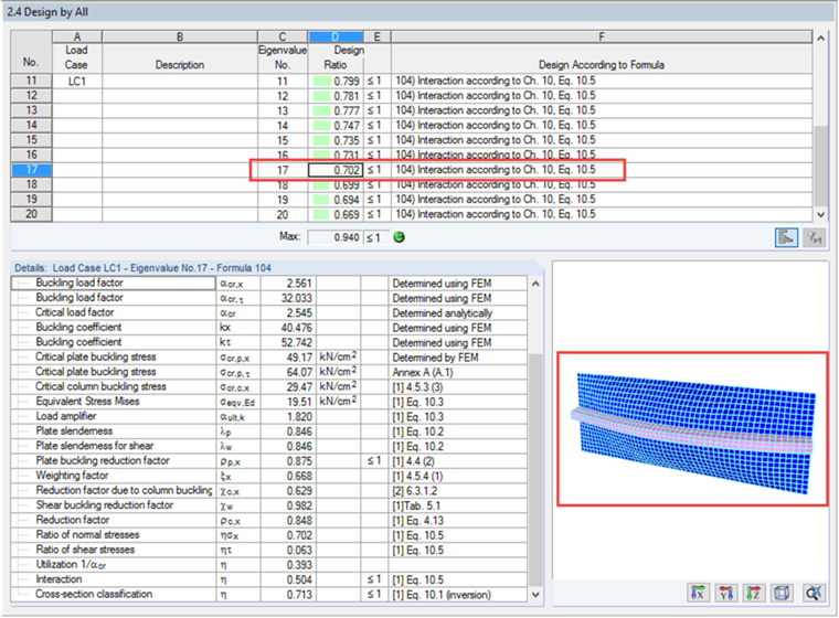
Now, you have to decide whether the corresponding subpanels are to be analyzed separately, or a global mode shape should be searched for in higher mode shapes. PLATE-BUCKLING provides the option to determine up to 50 mode shapes. The following figure shows Buckling Mode No. 17 for global failure of the stiffened panel.
Determination of Critical Plate Buckling Stresses
Based on the design of the stiffened plate and by using the corresponding global mode shape, the calculation of the critical plate buckling stresses according to [1], Annex A, can be performed using the buckling values and the critical buckling stress.
As an alternative, there are the analytical formulas for the calculation of critical plate buckling stress provided in [1], Appendix A. However, you should respect the following boundary conditions when applying them:
- At least three longitudinal stiffeners that can be applied as equivalent orthotropic plates
- One longitudinal stiffener in the compression zone of a buckling panel
- Two longitudinal stiffeners in the compression zone of a buckling panel
The calculation method for one or two longitudinal stiffeners in the compression zone is based on the elastically supported equivalent member. The critical buckling stresses determined by extrapolation to the compression edge result in critical plate buckling stresses.
Design Process on the Example
The following example shows the principle:
As already explained, the first mode shape shows the local buckling mode; therefore, it does not govern for the design of the stiffened plate. In this case, you can choose/decide on a further design process.
Step 1: Buckling analysis based on subpanels above and below the longitudinal stiffener
In a separate design case in PLATE-BUCKLING, the corresponding subpanel is defined with its dimensions, boundary conditions, and loads, and the buckling analysis is performed for the unstiffened buckling panel.
Step 2: Buckling analysis for the governing global mode shape of the subpanel
PLATE-BUCKLING not only allows the analysis of up to 50 mode shapes, it can also be useful for all the corresponding buckling analyses. In the following example, the governing mode shape (Mode No. 17) is used for the design of the entire span.
At this point it should be noted that, as an alternative, the design could be performed in Step 2 with the help of the analytical calculation methods described in Annex A.2 to determine the critical buckling and plate buckling stresses. However, since the global mode shape of the subpanel could be clearly found here, this is not necessary for this example.
Summary
Manual calculations of stiffened buckling panels are very difficult and time-consuming and in many cases, they are impossible without numerical calculations. PLATE-BUCKLING software provides a solution for such problems and allows for efficient plate buckling analyses.
References
| [1] | DIN EN 1993-1-5. (2019). Eurocode 3: Design of Steel Structures – Part 1–5: Plated Structural Elements, DIN EN 1993-1-5:2019-10. |
| [2] | Klöppel, K., & Scheer, J. (1960). Buckling Values of Stiffened Rectangular Plates, Volume 1. Berlin: Wilhelm Ernst & Sohn. |
| [3] | Klöppel, K., & Möller, J. (1968). Buckling Values of Stiffened Rectangular Plates, Volume 2. Berlin: Wilhelm Ernst & Sohn. |