The basic components of a rigid bolt connection are:
- Column web field with shearing stress
- Column web with transversal compression
- Column web with transversal tension
- Column flange with bending
- End plate with bending stress
- Girder or column flange and web with compressive stress
- Girder web with tensile stress
- Bolts with tensile stress
- Bolts with shear stress
- Welds
- Tapers
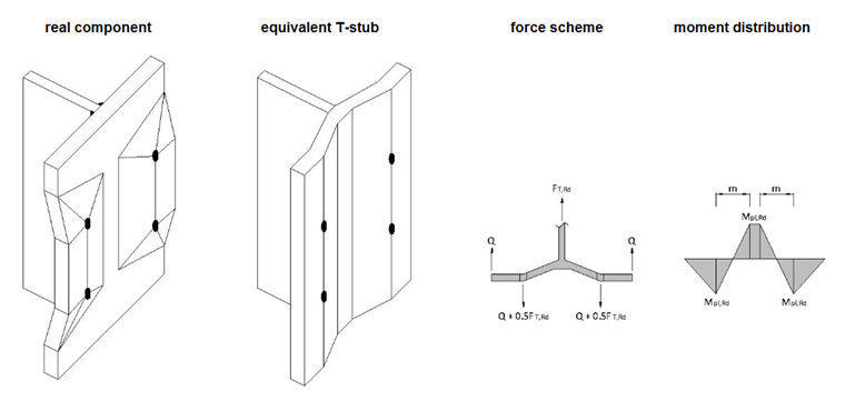
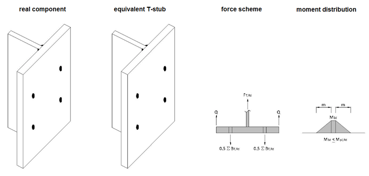
While design checks of the most basic components can be carried out relatively simply and quickly using the conventional formulas, the proof design of the end plate with bending stress, as well as the column flange with bending, is a time-consuming task. For these two components, an equivalent T-stub flange is used as the analytical model.
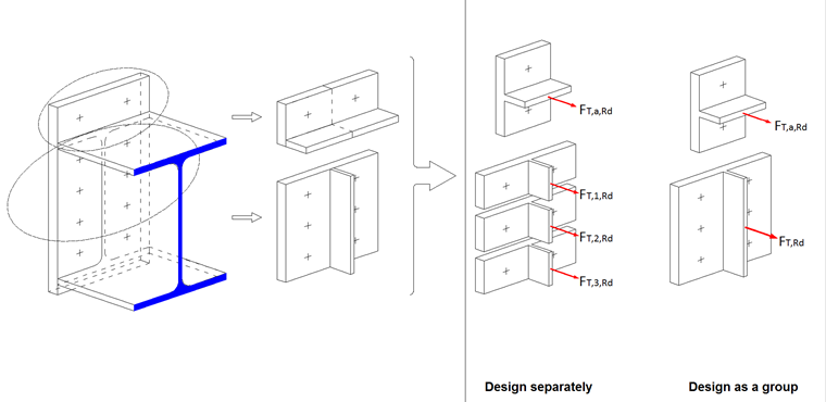
T-Stub Flange
A T-shape is cut out of the actual model. Bolt rows subjected to tensile stress are considered and evaluated, once separately and once as a group. The governing load-bearing capacity is determined from the lowest resistance of the sum of the individual bolt rows or the group value. The bolts in the bending compression area are used for the shear force transmission. The bolt rows are combined in bolt groups, which lie within the flanges or stiffeners. For the design of the end plate with bending stress, the T-stub is created from the end plate with a girder web for the internal bolt rows; in the case of an overhanging end plate with the external bolt row, the T-stub of the end plate corresponds to the girder flange. In order to be able also to design the overhanging part of the end plate, this will be divided and mirrored to the equivalent T-stub flange.
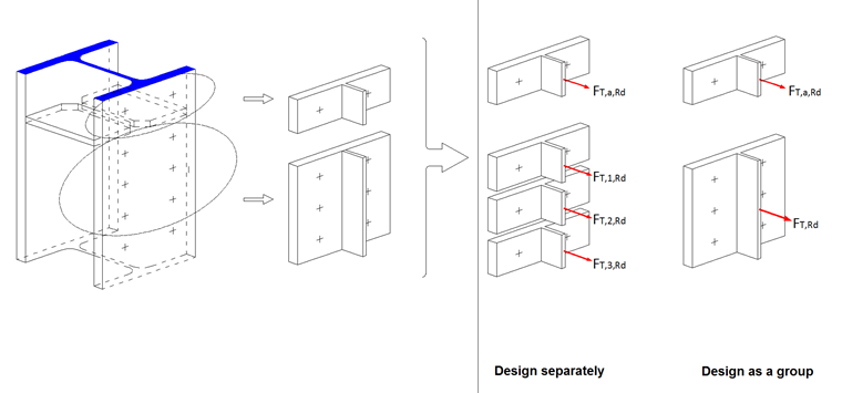
For the design of the column flange with bending, the T-stub is created from the column flange and the column web.
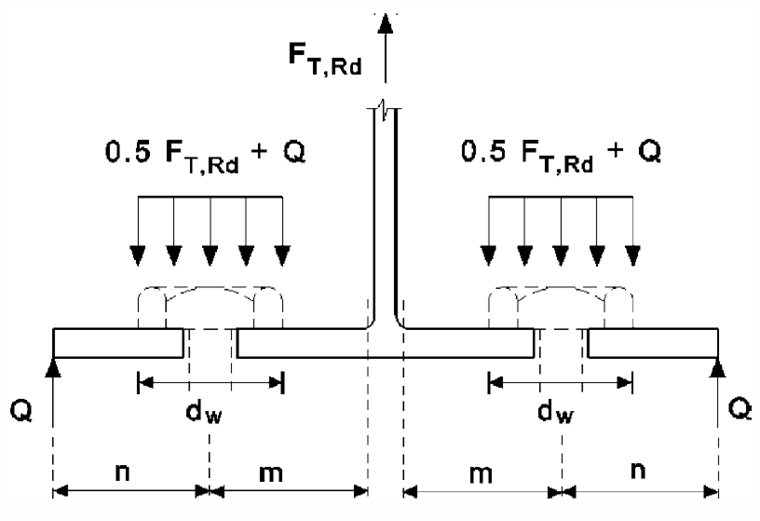
Contact force Q, which may occur between the free edge and the bolt row, is applied as the resultant of the surface pressure in the contact gap at the boundary point of the stub flange. Significantly higher load-bearing capacities with the contact forces can be achieved, so when modeling a connection, it is thus reasonable to arrange the position of the bolts in such a way that a restraint can also occur. For example, the contact force can be enforced by arranging a larger spacing of the bolt row from the girder web.
Failure Modes
Three failure modes are possible.
Mode 1: Pure Flange Yielding
In the case of a soft end plate, plastic hinges arise on the bolt axis and near the stub web without reaching the bolt breaking force. The load-bearing capacity of the equivalent T-stub flange can be calculated using two different methods, provided that supporting forces can occur. RF-/FRAME-JOINT Pro applies Method 1.
If no contact forces result from the calculation, the load-bearing capacity is halved. The same failure mode then also arises in Mode 2.
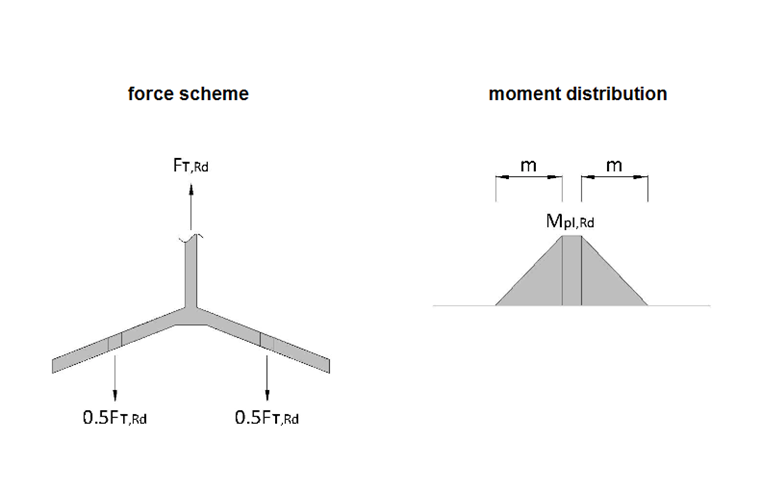
Mode 2: Simultaneous Bolt Failure with Flange Yielding
In the case of optimum accordance between the end plate thickness and the bolt diameter, a plastic hinge arises near the T-stub web and the bolts fail.
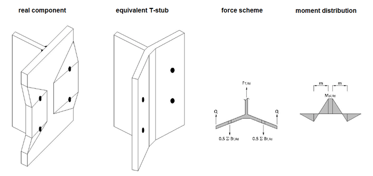
Mode 3: Bolt Failure
In the case of a rigid end plate and undersized bolts, these fail with no plastic hinges arising. This failure mode should be avoided as much as possible, since the connection becomes inefficient in this case.
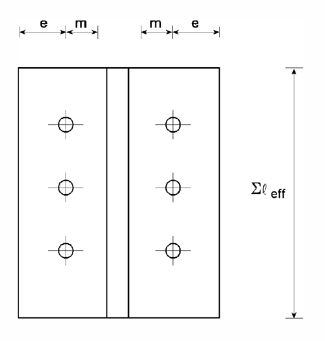
Effective Lengths
The effective lengths are required for determining the plastic moment resistance of the T-stub and need not necessarily match the actual lengths of the model.
By using the effective lengths on the equivalent T-stub, the spatial environment of the real connection is taken into account, so you obtain the same load-bearing capacities of the design model and the actual model.
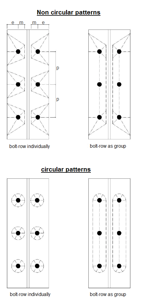
Depending on the geometry and failure mode, the end plate can adopt a circular or rectilinear yield line pattern, which can strongly influence the effective lengths of the T-stubs. In the case of the plastic failure of the end plate, a yield cone arises, which cannot be formed completely in Mode 2 and thus takes a non-circular yield pattern.
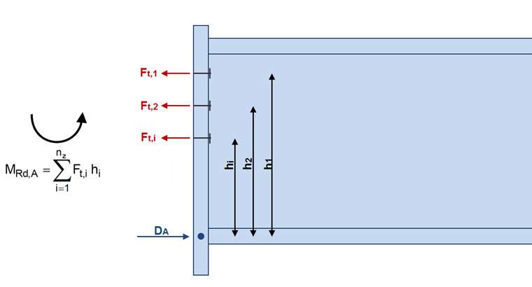
Determining Moment Resistance
The moment resistance of a connection is calculated from the sum of the determined tension resistance of each bolt row multiplied by the respective spacing to the compression point.
If the tension resistance resulting from the design of the bolt rows as a group is lower than the sum of the individual T-stub flanges, the respective row may only apply the component that contributes to the total load-bearing capacity of the bolt group.
The central axis of the compression flange should be assumed as the compression point.