


Determining Wind Loads from ASCE 7-16
Table 29.1-2 in ASCE 7-16 [1] outlines the necessary steps to determining the wind loads on a circular tank structure according to the Main Wind Force Resisting System (MWFRS).
Step 1: The Risk Category is determined from Table 1.5-1 [1] based on the use or occupancy of the building. Dome structures may be utilized as storehouses, which pose a relatively low risk to human life. On the other hand, domes are also used in the design of sports stadiums, which can have an extremely high impact on human life in the event of a failure.
Step 2: After determining the Risk Category from Step 1, the Basic Wind Speed (V) can be found in Figs. 26.5-1 and 26.5-2 [1]. These figures display the 3-s gust wind speed maps for the United States, which vary depending on the location and Risk Category of the structure. Linear interpolation is permitted between the given contour lines.
Step 3: There are multiple wind load parameters required in this step which ultimately influence the wind load pressure.
The Wind Directionality Factor (Kd) from Table 26.6-1 [1] is given as 1.0 for circular domes and round tanks.
Considering two wind directions, the Exposure Category is set based on the topography, vegetation, and other structures on the upwind exposure side. The higher the Exposure Category (that is, Category D), the more exposed the structure may be.
The Topographic Factor (Kzt) considers wind speed-up over hills, ridges, and escarpments. This value is calculated in Equation 26.8-1 [1] using the factors K1, K2, and K3 given in Figure 26.8-1 [1].
Kzt = (1 + K1K2K3)²
The K factors from Figure 26.8-1 [1] depend on the terrain such as hill height (H), distance from the crest to the site of the building (x), height above the ground surface (z), and so on.
Table 26.9-1 [1] gives the Ground Elevation Factor (Ke) based on the structure's elevation above sea level. This factor can also be conservatively taken as 1.0 for all elevations.
The Enclosure Classification can be determined in Section 26.2 [1]. Openings in the structure may have an influence on this classification. If a structure complies as both "open" and "partially closed", the more conservative "open" category shall be applied. In many cases, for storehouses, the enclosure classification is considered "closed". For sport stadiums, however, this may depend on the structure's wall openings, retractable roof, and so on.
Depending on the Enclosure Classification, the Internal Pressure Coefficient (GCpi) as both a positive and a negative value to account for pressure acting toward and away from the internal surfaces can be found in Table 26.13-1 [1].
The Gust-Effect Factor (G) depends on the structure's stiffness definition as rigid or flexible from Section 26.2 [1]. The fundamental natural frequency plays an important role in determining this classification. The RFEM add-on module RF-DYNAM PRO Natural Vibrations can be utilized to find the structure's fundamental natural frequency. Section 26.11 [1] gives the relevant formulas to calculate G for rigid or flexible structures. Alternatively, 0.85 is permitted to be used for rigid structures only.
Step 4: The Velocity Pressure Exposure Coefficient (Kz) can be found in Table 26.10-1 [1] based on the Exposure Category. Two Kz values should be determined on the basis of the mean wall height of the dome and the mean roof height of the dome. Linear interpolation can be used for intermediate height values.
Step 5: The Velocity Pressure (qh) is determined from Equation 26.10-1 [1].
qh = 0.00256KzKztKdKeV²All variables in this equation were determined in the previous steps. Two qh values should be calculated to be used in a later step. The first will be qh at the height of the wall centroid and the second based on the mean dome roof height, which are dependent on the Kz values from Step 4. The subscript notation qh vs. qz is used interchangeably in Equation 26.10-1 [1], depending on the velocity pressure evaluated for walls versus the roof, respectively.
Step 6: The Force Coefficient (Cf) for walls of an isolated dome in Section 29.4.2.1 [1] can be set to 0.63, where H/D is in the range of 0.25 to 4.0 with H = solid cylinder height and D = diameter. Cf for walls of grouped domes is calculated on the basis of Figure 29.4-6 [1].
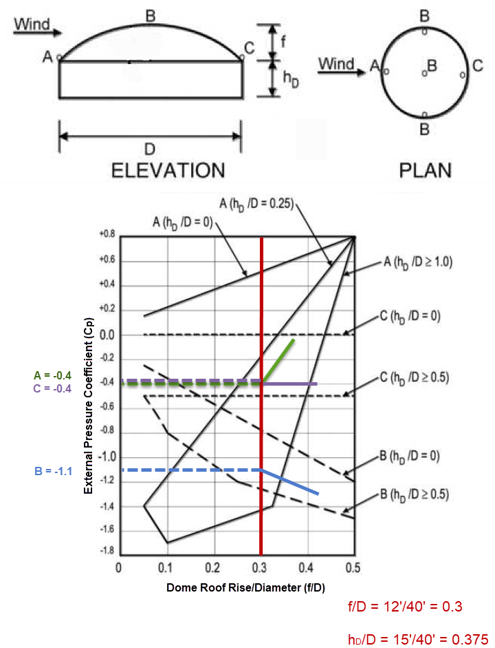
Step 7: The External Pressure Coefficient (Cp) for a dome roof with a roof angle greater than 10° is determined in Figure 27.3-2 [1]. Based on the dimensions for the dome rise, height to the base of the dome, and diameter, three Cp values will be determined from this figure for locations A, B, and C specific to the structure (see Figure 01).
Two wind load cases are to be considered along the perimeter and height utilizing these various Cp values:
- Case A: Cp values between A and B and between B and C shall be determined by linear interpolation along arcs on the dome parallel to the wind direction.
- Case B: Cp shall be the constant value of A for θ ≤ 25° and shall be determined by linear interpolation from 25° to B and from B to C.
Step 8: The Wind Force (F) for walls is calculated in Equation 29.4-1 [1].
F = qzGCfAf
The Wind Force (F) can in turn be divided by the Projected Area normal to the wind (Af) to find the wall pressure for application as a surface load in RFEM. Keep in mind that qz is the Velocity Pressure previously calculated in Step 5, but used with an alternative subscript, as both are used interchangeably and evaluated at the centroid of Af (the mean wall height).
The Design Pressure (p) for both an isolated and grouped dome roof is found with Equation 29.4-4 [1].
p = qh(GCp - GCpi)
The qh value from Step 5 is evaluated at the mean dome roof height. G and GCpi are determined in Step 3, while multiple Cp values for a domed roof > 10° are found in Step 7.
Wall Pressure Application in RFEM
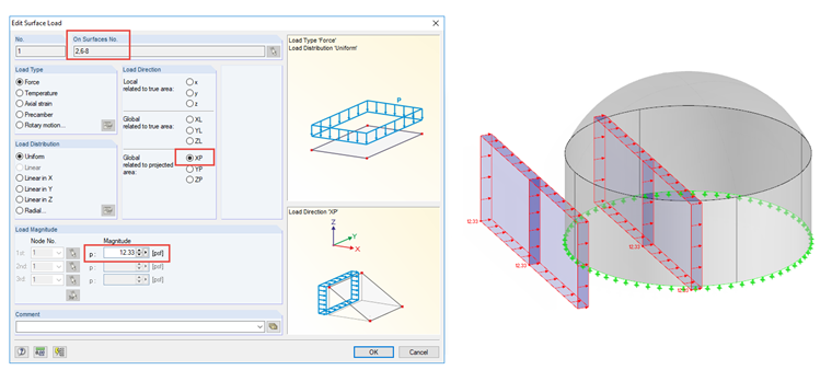
The wind pressure is determined from Step 8 in the sequence above. The wind pressure should be applied to the projected area normal to the wind in both the windward and leeward directions. This projected area load can easily be applied to the face of the dome walls under the menu option "Insert" → "Loads" → "Surface Loads". In the corresponding dialog box, you can select the wall surfaces first and define the projection direction (see Figure 02).
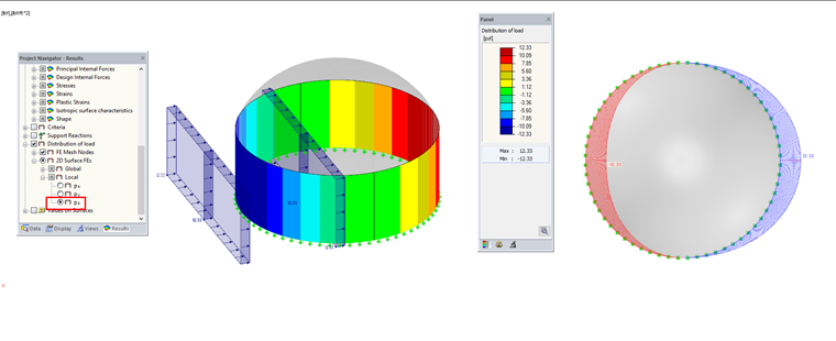
To visually check the applied loads, select the "Distribution of load" check box in the Results navigator (see Figure 03) after running the analysis. It is sufficient to calculate one iteration for the corresponding load case. This can save significant time rather than solving all load cases and combinations for larger structures with a fine FE mesh. The accuracy of the load distribution depends on the FE mesh. The smaller the FE mesh, the more accurate and exact the load distribution magnitude will appear.
Dome Roof Pressure Application in RFEM
As explained in Step 7 above, Figure 27.3-2 in ASCE 7-16 specifies the external pressure coefficients for domes with circular bases. Note 4 in Figure 27.3-2 [1] indicates the external pressure coefficients are constant along any plane perpendicular to the wind direction. Figure 27.3-2 [1] mentioned in Step 7 displays the external pressure coefficients to be applied to three areas along the dome roof (A, B, and C). Two load cases shall be considered as further specified in Figure 27.3-2 Note 1 [1]. Both cases call for locations between points A, B, and C to be determined by linear interpolation.
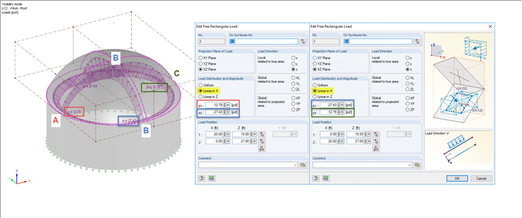
The external pressure coefficient has a value of -0.4 for Point A, -1.1 for Point B, and -0.4 for Point C (see Figure 01). According to Equation 29.4-4 [1] and Step 8 above, the wind pressure results are -12.79 psf / -3.94 psf for Point A, -27.43 psf / -18.573 psf for Point B, and -12.79 psf / -3.94 psf for Point C for a +GCpi and -GCpi, respectively.
These loads can easily be defined in RFEM with free rectangular loads which can be generated under the menu "Insert" → "Loads" → "Free Rectangular Loads". In addition to defining the projection plane and the load direction, it is possible to consider a linear function for the load distribution that covers the interpolation between the individual points (A, B, and C). Two free rectangular loads are created. One is designated for areas A to B, the second for areas B to C (see Figure 04).
The load distribution function previously mentioned under the Results navigator will display the applied wind load on the dome roof. For a clear look at the load effect along a single cut line of the roof, you can optionally create a section (see Figure 05).
