


Load Combinations
In [1], Section 3.2(2)P, an impact is defined as an accidental design situation. Thus, Equation 6.11b applies to the combination of actions. The choice between the frequent value Ψ1,1 ⋅ Qk 1 and the quasi-permanent variable Ψ2,1 ⋅ Qk 1 depends on the governing accidental design situation.
In [2] NDP to A.1.3.2, for example, in the case of a vehicle crash, it is specified that application of the quasi-permanent value Ψ2,1 ⋅ Qk,1 is allowed. Hence, snow loads and wind loads for locations in CEN member states with a height less than 1,000 m above sea level do not have to be considered in case of a vehicle impact, because their combination coefficients Ψ2,1 are usually defined as 0.0.
Defining Accidental Action
Now, we have to define the type and size of the impact. Part 1-1 of the Eurocode 1 [3] in Section 1.1(6) refers to Part 1-7 [4] where accidental actions are explained. Two methods are recommended in Section 4.2(1):
- Determination of impact loads with a dynamic analysis
- Definition of impact loads as equivalent static force
For information on the dynamic impact design, see Appendix C. This annex distinguishes between a "hard impact", where the energy is mainly dissipated by the impacting body, and a "soft impact", where the structure is designed to deform in order to absorb the impact energy. According to Annex C.2.1(1), calculating with an equivalent static force for a "hard impact" is allowed. In the event of a car crashing into a carport, a hard impact is assumed and the content of this article refers to the determination of the equivalent static force.
In [4], Table 4.1, an equivalent static force Fdx in the direction of normal travel of 50 kN is proposed for passenger cars in parking garages. Transverse to the direction of travel, this results in the force Fdy of 25 kN. Due to the size of the load, it will probably be possible only very rarely to realize economical dimensioning of the column cross-sections of a carport. It should also be mentioned that collisions on lightweight structures are excluded in Section 4.1(1), thus Table 4.1 is not valid and reference is made to the National Annex. The installation of an impact protection that absorbs the impact in front of the column in order to carry out an economical design of the columns is not likely to be an option. The National Annex of Germany [5] describes a statically equivalent impact force of 10 kN for both directions for passenger cars ≤ 30 kN in Table NA.2-4.1 for single and double garages as well as carports.
If the National Annex of a country does not provide any further information, it is worth taking a look at [2] Annex B. In Equation B.1, the horizontal equivalent load for a fall protection is described. This results in:
According to Annex B(3) in [3], the following assumptions are selected:
- m = 1,500 kg
- δc + δb = 100 mm
- v = 1.39 m/s
The impact velocity v deviating from B(3) is assumed with 5 km/h according to [4], Table C.1 for parking garages, which corresponds to 1.39 m/s. This results in an equivalent load of:
Position of Accidental Action
According to [4], 4.3.1(3), applying the impact force of passenger cars at a height of 50 cm above the top edge of the road is allowed. In [3], Annex B, 37.5 cm are specified for passenger cars with a maximum vehicle mass of 2,500 kg. Since the height of a passenger car's bumpers is not standardized in most countries, the engineer has to decide at which height the equivalent load will be applied. The German Annex [5] recommends a height of 50 cm for passenger cars.
Complete Failure of Structural Components as Option
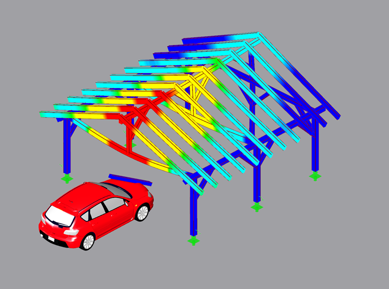
There is also the option to analyze the effects of complete failure of the affected structural component on the entire structure (Image 02). Depending on how the component is fixed, such an analysis can be useful.
Designing Carport Column for "Impact" Load Case in RFEM/RSTAB
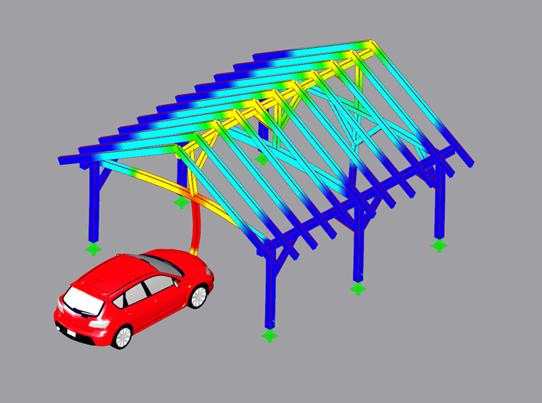
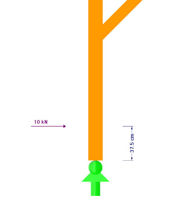
For the carport shown in Image 01, the impact of a passenger car on the central column will be simulated. The design will be performed according to the German Annex in this example.
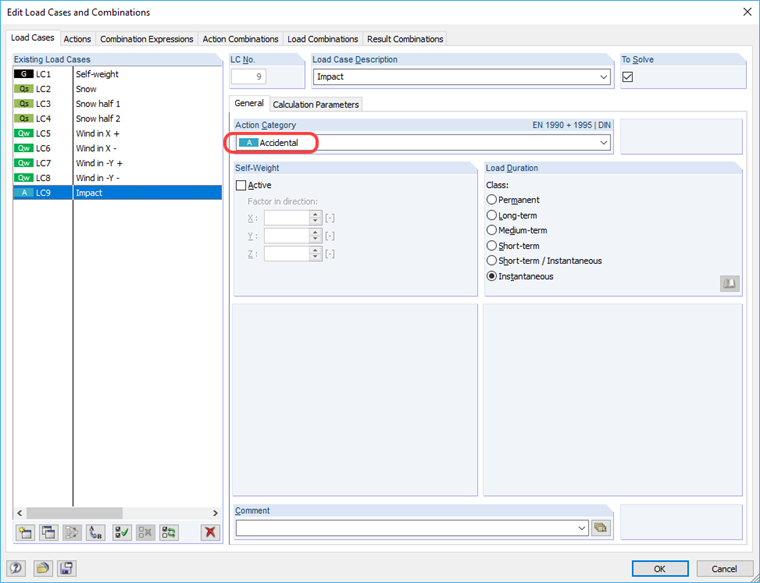
For this purpose, a new load case has to be created first where the static equivalent load is defined. If the automatic load combination is used, the "Accidental" action class should be assigned to this load case.
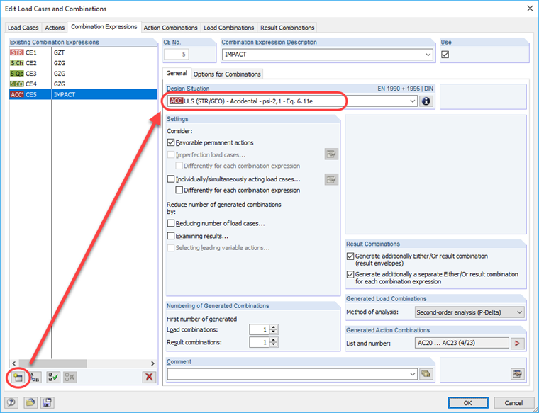
Afterwards, a new combination expression is created with the accidental design situation according to [2], Equation 6.11e.
In this example, the distance of the equivalent load from the member start of 37.5 cm is selected, because the fastener (in this case, the height of the column footing) is not taken into account in the structural analysis.
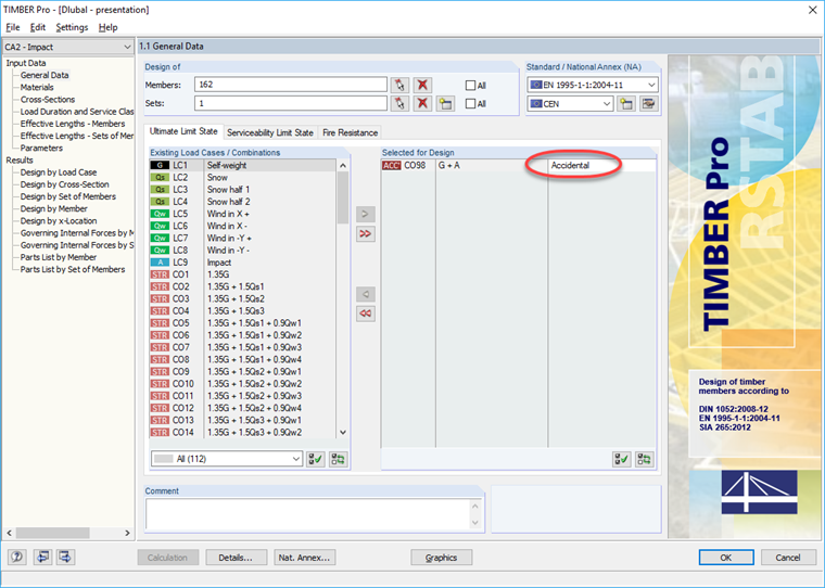
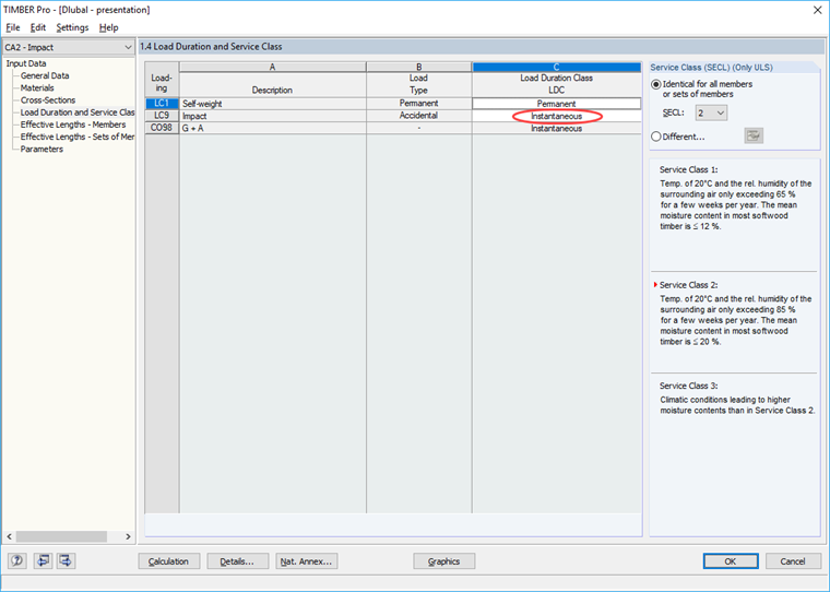
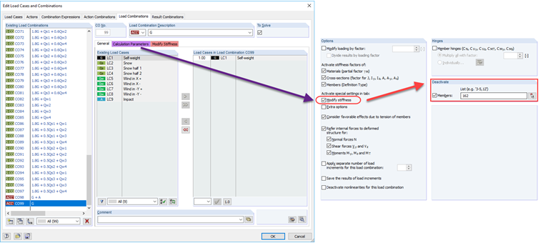
The timber structure is designed with the RF-/TIMBER Pro add-on module. The corresponding model files for RFEM and RSTAB are available at "Downloads" at the end of this article. In TIMBER Pro Case 2, the accidental design is carried out by selecting the corresponding load combination. Since the snow load and wind load do not have to be combined with the impact in this case, only the self-weight and the impact itself have to be considered. If the load combinations are created manually, make sure that the "Accidental design situation" is assigned to the corresponding load combinations (Image 06) and the correct load duration class, "Instantaneous" (Image 07).
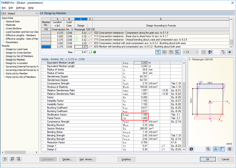
By this assignment, the accidental design situation in the ultimate limit state is considered with a partial safety factor of 1.0, as required in [6]. Moreover, in this case, the strength is multiplied by a kmod of 1.1 (Service Class 2) because of the instantaneous load duration. In this example, the column has a ratio of 0.47 ≤ 1.00 and the impact of the passenger car is thus designed. The design works even with a kmod value of 0.9 (Service Class 3).
As already explained, it is worth taking a look at the complete failure of the column (Image 02). For this purpose, it is not necessary to consider failure or deletion of the member in a separate file. The column can be easily deactivated for specific load combinations. For the complete failure of the column, a new load combination will be created where only the self-weight is included and the column is deactivated in the calculation parameters.
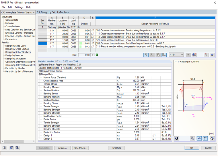
Since the structure is certainly supported immediately after the column fails, an "instantaneous" load duration can be applied for this load combination. The purlin design under self-weight for the accidental design situation amounts to 0.48 ≤ 1.00 (TIMBER Pro Case 3).
Designing Joints and Foundations
Furthermore, the fasteners must be checked in case of an impact. Therefore, it is necessary to verify that the column base and the connection of the column to the purlin above are dimensioned sufficiently. The type of the structure governs whether the impact load must be transferred into the foundation or not. In [5], NDP to 4.1 (1), Note 3, the transfer of forces generally does not govern for buildings. This statement is true for the carport mentioned in the example.