


The wind standard EN 1991-1-4 specifies a calculation concept with aerodynamic values and reduction factors for this case. These specifications finally yield a resulting wind force on the structural component. The wind pressure distribution around the structural component is not specified. The wind force is, therefore, based on the following relation:
|
cscd |
Two-part structural factor to take into account the fact that peak wind pressures do not occur simultaneously on the entire structure (cs), as well as the dynamic precamber caused by resonance-like structural vibrations due to wind turbulence (cd) |
|
cf |
Force coefficient for a building object or building object section |
|
qp(ze) |
Peak velocity pressure at the reference height ze |
|
Aref |
Reference surface for a building object or building object section |
If the component under consideration is assumed to be a rigid, unyielding body under a constant wind flow, determining the wind force can be simplified into the following law:
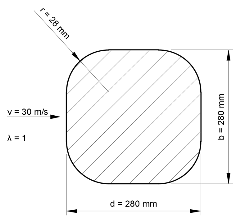
For a non-slender structural component with a quadratically rounded cross-section, the force coefficient cf is determined according to [1] as follows:
|
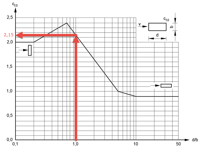
cf,0 |
Basic force coefficient of sharp-edged cross-sections |
|
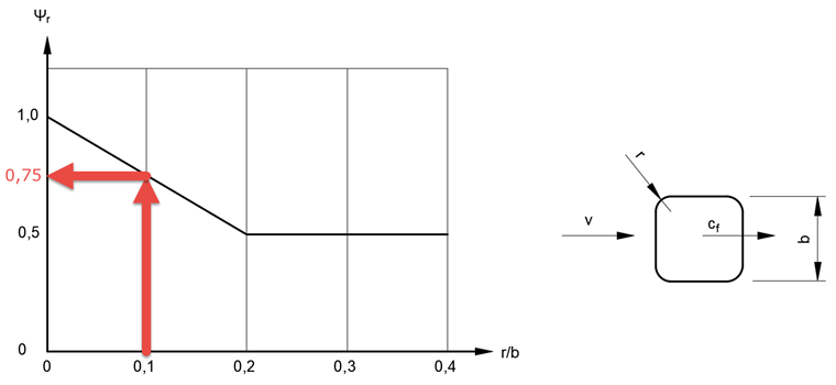
Ψr |
Reduction factor for considering the rounded corners of a quadratic cross-section |
|
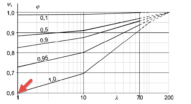
Ψλ |
Reduction factor for considering the effective slenderness λ, depending on the solidity ratio φ |
|
φ |
Solidity ratio for considering the permeability of windward surfaces |
Conventional Determination of Wind Load
According to [1], for these component properties,
a force coefficient cf = 0.97 results as an example.
This value is based on the basic force coefficient cf,0 = 2.15 dependent on the aspect ratio d/b = 280 mm/280 mm = 1,
the reduction factor Ψr = 0.75 dependent on the radius aspect ratio r/b = 28 mm/280 mm = 0.1,
and finally, the reduction factor Ψλ = 0.6 dependent on the slenderness λ = 1, assuming a fully closed component surface φ = 1.
The velocity pressure q = 563 N/m² applied to the reference surface Aref = 280 mm ⋅ 280 mm = 0.0784 m² results in the relation:
Thus, finally, a wind force Fw = 0.97 ⋅ 563 N/m² ⋅ 0.0784 m² = 43 N acts on the structural component in the wind direction.
Numerical Determination of Wind Load
If the wind pressure distribution over the component is also necessary in addition to this wind force Fw, a corresponding pressure distribution on the component can be calculated, for example, by means of a CFD analysis. Here, the component is imagined to be in a numerical wind tunnel and the pressure distribution on the component is determined depending on the resulting pressure and velocity distribution around the component.
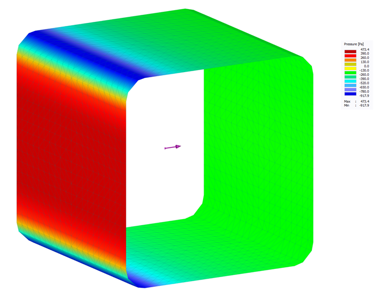
The RWIND Simulation program allows this numerical simulation of wind flows around buildings or other objects based on a 3D finite-volume mesh. The application automatically generates this mesh with mutually correlating element sizes adjusted to the model. The closer the finite-volume elements are to the model surface, the finer the mesh that is generated. The program uses the OpenFOAM mesh generator (SnappyHexMesh) for this process. The stationary SimpleFOAM solver for incompressible turbulent flows is used to calculate the wind flow and the wind pressure on the model surface.
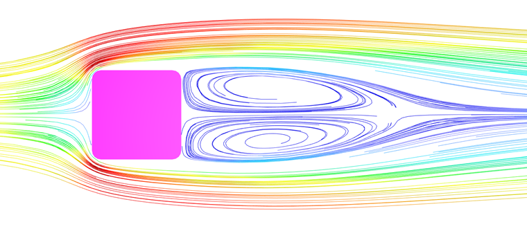
For the given example, an RWIND Simulation calculation results in a similar wind force Fw = 41 N. In addition to this resultant, the program also outputs the pressure and wind velocity distribution around the structural component, as well as the pressure distribution on the component.
