


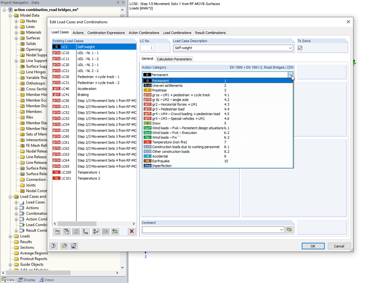
Action Categories
Load cases can be classified into the different categories of permanent actions (permanent loading, uneven settlements, prestress), variable actions (traffic, climatic actions), actions from construction stages and assembly, accidental actions, and actions from earthquakes.
In particular, when assigning traffic load cases, it is important to ensure that the load cases are already assigned to the correct load group. A simple example of a road bridge with two lanes explains the use of the automatic action combination according to EN 1990 + EN 1991-2 in RFEM.
Load Groups for Traffic Loads
By grouping the traffic loads according to EN 1991-2, the probability of simultaneously occurring maximum values of the traffic load's different components should be considered. RFEM and RSTAB only contain the traffic load groups for the loading of road bridges; there is currently no automatic combination available for the loading of railroad bridges.
The traffic load groups 1 to 6 for road bridges represent the following load situations.
| gr1a | Maximum vertical load due to traffic, LM1 |
| gr1b | Maximum vertical load due to traffic, LM2 |
| gr2 | Maximum horizontal load due to traffic |
| gr3 | Load on pedestrian and cycle paths (without road traffic) |
| gr4 | Load due to crowd of people |
| gr5 | Load due to special vehicles |
| gr6 | Load when replacing supports, stressed cables, or similar |
By assigning the traffic load cases to the correct action categories, the combination relations between these load cases are automatically regulated. In the example, this will be shown for the load groups gr1a and gr2. It is also possible to consider several load cases per load type; that is, as an area load applied by span, as in the example.
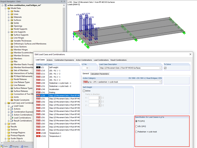
Traffic Loads in gr1a
Load model 1 for road traffic includes a uniformly distributed area load (UDL) and the corresponding concentrated loads in the tandem system (TS). These loads, together with the loads on pedestrian paths and cycle tracks, are assigned to group 1a. Alternative relations between all load cases marked as TS are automatically taken into account; the load cases marked as UDL or pedestrian path and cycle track can act simultaneously.
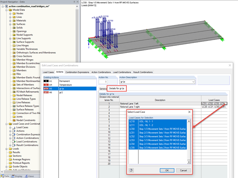
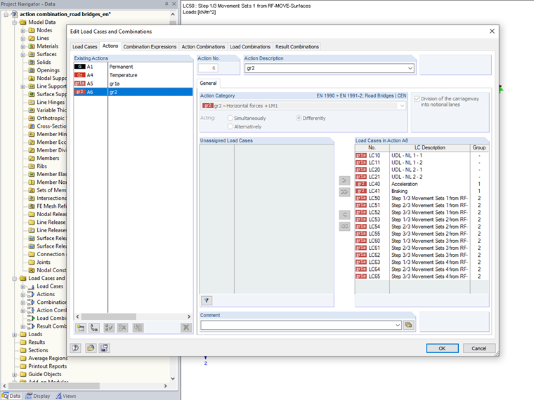
If you do not want to analyze only one possible location of the most heavily loaded lane 1, you can activate the "Division of the carriageway into notional lanes" option. Then, the respective load cases have to be assigned manually, depending on the direction. In the example, the location of Lane 1 on the left side of the bridge is analyzed first. For this, LC10 and LC11 were created as UDL, and LC50 through LC55 as TS. For the analysis of Lane 1 on the right side of the bridge, LC20 and LC21 have to be considered as UDL, and LC60 through LC65 as TS. The load cases LC30 and LC31 are marked as pedestrian path and cycle track, and are thus additionally applied regardless of the location of the first lane.
Traffic Loads in gr2
The horizontal loads from braking and starting, as well as from centrifugal forces, are to be arranged in gr2. Alternative relations between a load type's load cases are created automatically. According to the specifications of EN 1991-2, the vertical loads from load model 1 are additionally considered in load group gr2 with the combination factor psi 1 for the frequent combination.
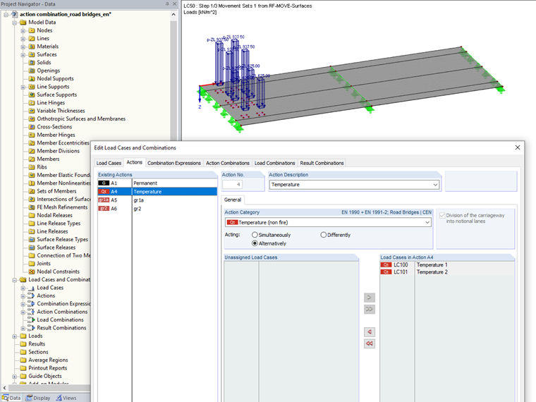
Other Action Categories
For load cases of other action categories, the load cases' simultaneous or alternative effect can be manually defined using the familiar input windows. In the example file, two load cases with temperature loading have been added (LC100 and LC101). These two load cases are intended to represent heating or cooling of the bridge surface and are, therefore, defined as alternative load cases.
Action Combination in ULS
For the ultimate limit state, the possible action combinations are now generated in the example. The traffic load groups are always applied as variable actions acting alternatively to each other. Other actions are combined with these traffic load groups according to the selected combination expression.
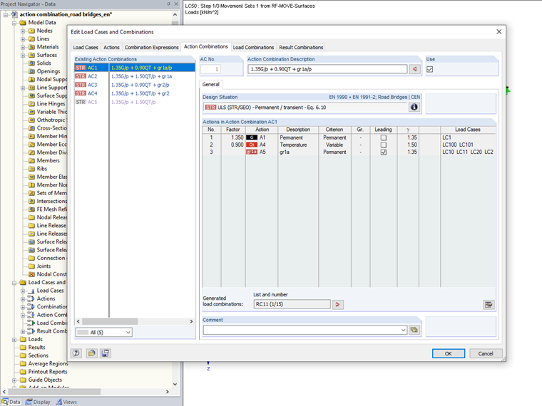
Here, the traffic load groups are not combined with the loads from the construction work or their corresponding wind loads. Likewise, the different action categories of the wind loads are considered as alternative, and loads from the construction work are only combined with the corresponding wind action.
Additional setting options allow for a user-defined combinatorics adjustment; for example, to consider the traffic load groups having snow and wind actions at the same time.
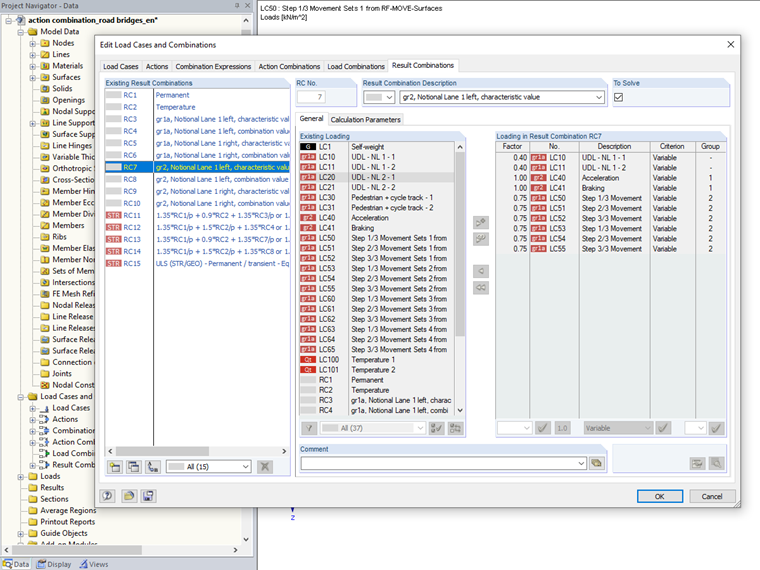
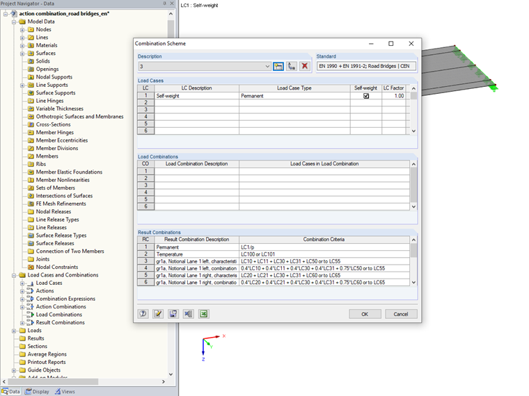
Result Combinations for ULS
Thus, in the combination for the ultimate limit state, both the characteristic value for the combination as a leading action, and the value reduced by the combination factor, are required from each traffic load group for the combination as an accompanying action. When considering the traffic load from gr1a for the two cases of the arrangement of the main loaded lane, this combination is formed for both cases. In this example, the result combinations RC3 and RC4 result for Lane 1 on the left, and RC5 and RC6 for Lane 1 on the right. Therefore, four result combinations are generated as well for load group gr2 in order to take account of this division of lanes. The final combination is done by creating the result combinations RC11 to RC15.
Notes
With the automatic action combination available in RFEM and RSTAB, you can create either load combinations or result combinations. The example shows the creation of result combinations. The load groups and lanes are taken into account by creating separate sub-combinations. For the option using load combinations, the relations between the load cases are taken into account via the input window "Settings – Individually/Simultaneously Acting Load Cases", which is automatically filled.
One special feature is the application of the partial safety factor for uneven settlements. When load combinations are selected, the factor for nonlinear elastic calculation is used automatically. When selecting result combinations, the factor for linear elastic calculation is applied.
If necessary, the current creation of load and result combinations can be extended manually by adjusting the partial safety and combination factors, or by subsequently using a combination scheme.
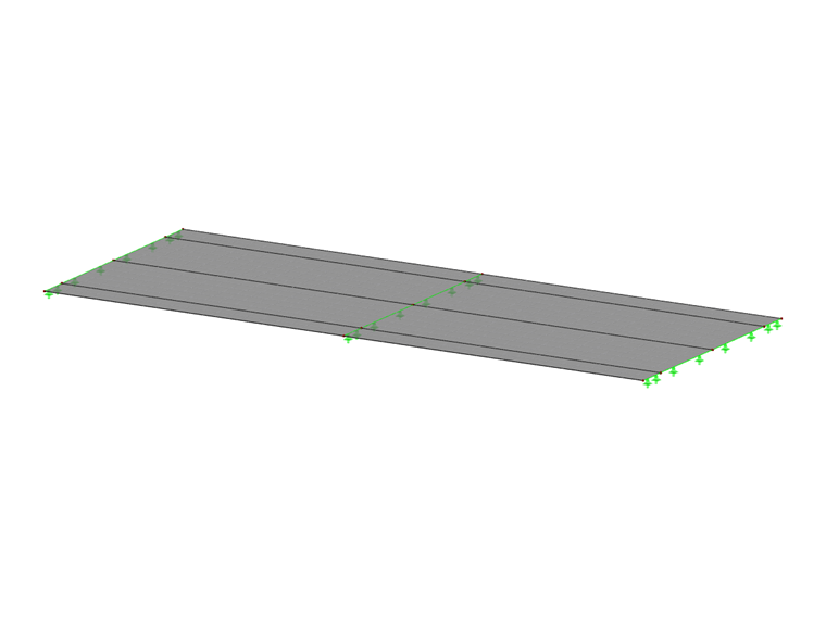
Model and loading were only created to explain the combinations. Neither the size nor the load arrangement should be transferred to your own application cases without checking.
