


This article describes the modeling of a Kármán vortex street in RWIND.
For certain Reynolds number ranges, a street of vortices is formed behind objects that are narrow but high. In areas with many high-rise buildings and a trend towards narrow skyscrapers, in particular, these vortices can have an impact on the wind loads of the surrounding buildings. The following shows the vortex formation as a function of the Reynolds number according to [1].
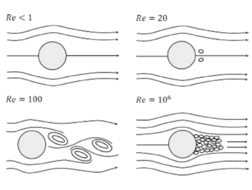
The well-known vortex street develops on a Reynolds number basis of about 100. When the number increases, the flow becomes turbulent. So far, satisfactory results have only been achieved in a Reynolds number range that is too high. Find an example where Re = 10e7 below.
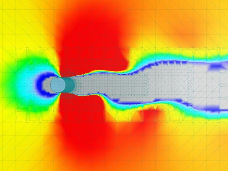
Hence, the inlet velocity had to be set much higher than calculated in order to trigger the desired behavior. An exact limit velocity could theoretically be identified, but would require many individual simulations (even with a linearly increasing wind profile), which was rejected due to time constraints. In addition, the vortex shedding frequency does not seem to conform to the theory. Since the shedding frequency depends on the Strouhal number and thus the inlet velocity, this behavior was to be expected.
The mesh density is probably the most important influencing factor in the correct formation of a vortex street. In order to save resources, the mesh density in RWIND is reduced by increasing distance from the analyzed object in the wind tunnel. This simplification is very useful for individual buildings, but makes modeling the Kármán vortex street more difficult. Therefore, a mesh refinement, such as of a section over the height of the structure over the full length of the wind tunnel, starting with the structure's depth, makes sense. The effect of such a refinement is shown below.
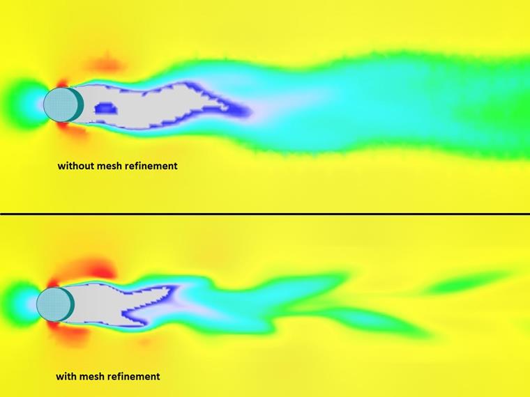
In the context of the present analysis, it has not been considered to what extent a mesh refinement affects the ultimate pressures on surrounding buildings. This needs further analysis using future modeling.
The following image is the result of an adapted color scheme and refined mesh. The slightly tilted view enables a better distinction between the different shades of red.
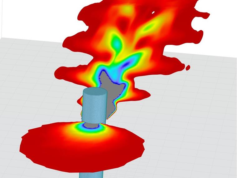
What is interesting is the direction of the velocity vectors. The greatest turbulence, which is directly behind the structure, shows the desired chaotic distribution of the directional vectors, as would be expected with a vortex. However, smaller vortices at a greater distance from the structure do not show this behavior. Although the false-color image of the magnitude-based velocity distribution suggests smaller vortices, all direction vectors point in the direction of the inflow. This behavior makes no sense in terms of fluid mechanics, but no specific cause can be identified.
Further optimization of the vortex street would certainly be possible with an even finer mesh. It is also plausible that an even finer refinement could also correct the anomaly of the directional vectors. However, this results in significantly higher memory and computing requirements. A mesh refinement that is as small as possible but as large as necessary would be advisable. The cylinder's top third, including a sufficient distance to the top nodes, would probably be best suited for this.
All in all, the modeled vortex street shows relatively good results with regard to the velocity and thus the pressure profile. In detailed aspects, such as the directional vector distribution and the emission frequency, the approach presented in this article probably fails due to the limitations of the solver itself. It is advisable to repeat this calculation with the latest versions of RWIND.