


Defining Plastic Hinges in RFEM 6
Plastic hinges are imperative for the Pushover Analysis (POA) as a nonlinear static method for the seismic analysis of structures. In this analysis, a pre-determined lateral load pattern is applied to the structure and increased steadily to identify yielding and plastic hinge formations and the load at which failure of the various structural components occurs.
The nonlinear behavior of the structure is represented by the Capacity Curve or Pushover Curve as a load-deformation curve of the base shear force versus the horizontal roof displacement of the building.
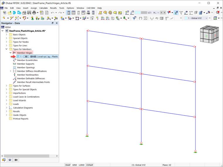
Pushover curves can be created using plastic hinges. In RFEM 6, plastic hinges can be defined as member hinges available as “Types for members” in the navigator data (Image 1).
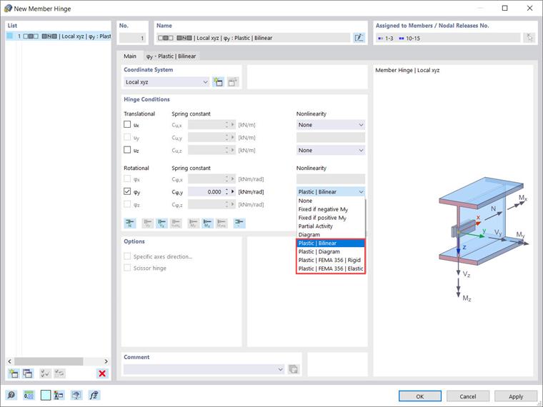
Four possibilities are available for selection with the “Plastic” option of a nonlinearly acting hinge component (Image 2):
- Bilinear
- Diagram
- FEMA 356 | Rigid
- FEMA 356 | Elastic
Hinges according to EN 1998-3 are in the development phase and will be available soon.
As an example, a plastic hinge with the option “Plastic | Bilinear” will be created in this article. By selecting this option, a new tab is available for you to define the properties of the plastic areas (Image 3). The properties in the negative and positive zones are the same, and therefore the “Antimetric” check box is ticked. However, it is also possible to assign different properties in the negative and positive zones by clearing this check box.
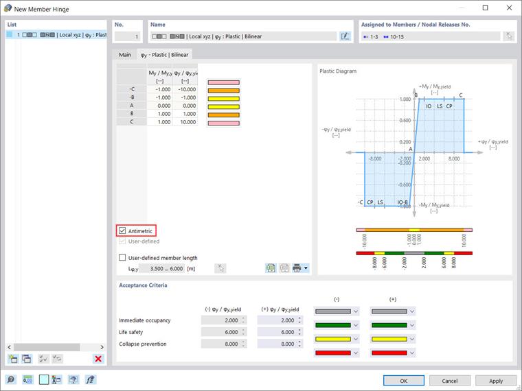
The properties of the plastic areas are associated with the values of the following ratios: “My/My,yield” and “φy/φy,yield” (Image 3). With a value of 1 for My/My,yield, for example, the cross-section begins to yield when reaching the plastic moment.
At this point, please note that appropriate definition of the member length is also important because it affects the stiffness calculation of the plastic hinge. Although the member length is recognized automatically from the lengths of the members to which the hinge is assigned, you have the option to specify a user-defined member length for the hinge by ticking the associated check box.
Next, the “Acceptance Criteria” section in this dialog box allows you to define the limit values of the yielding criteria to be applied for the safety of the building (Image 3). The description of the acceptance criteria can be found in the standards.
For instance, the value of 6,000 for φ/φyield implies that the critical value for “Life safety” is reached as soon as the plastic deformations are six times greater than those occurring when the yield strength is reached.
Finally, the assigned properties of the plastic hinge as well as the areas of the acceptance criteria are reflected in the “Plastic Diagram” section in the upper right corner of the dialog box (Image 3).
