If you have already modeled steel connections in RFEM 6, you are probably familiar with the Steel Joints add-on. This add-on allows for the analysis of connections on the basis of an FE model. The design checks are carried out for various connection types for rolled and welded cross-sections. The input and result evaluation are completely integrated in the user interface of the structural FEA software RFEM.
Due to this add-on, steel joints can be created in RFEM 6 by means of the simple and familiar input of predefined components. The library for these components is constantly being expanded to make it even easier for our customers to model steel connections.
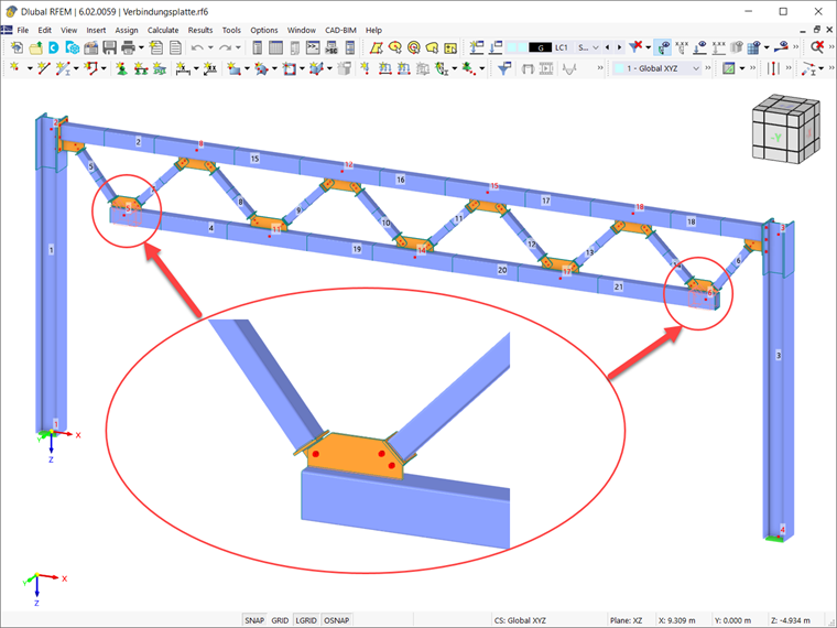
This article introduces the Connection Plate component and you can see an example of how to use it in order to model a steel joint to be assigned to nodes No. 5 and No. 6 (Image 01).
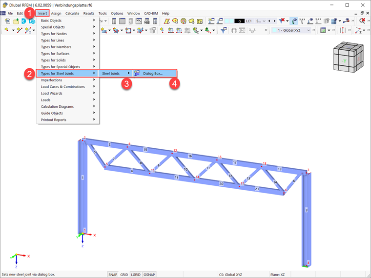
As shown in Image 01, the steel connection to be created connects members No. 4, No. 5, and No. 7 on the one hand and members No. 21, No. 6, and No. 14 on the other hand. To start creating the steel joint, you need to open the “New Steel Joint” window as shown in Image 02.
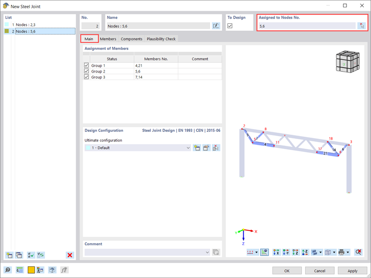
Once the “New Steel Joint” window is open, in the “Assigned to Node” section you need to specify all the nodes intended for the design. You can adjust the number of nodes by typing them in or entering graphically using the “Select individually” button. This joint is to be assigned to nodes No. 5 and No. 6, so these nodes are entered in this section (Image 03). As soon as you select a node for design, the program assigns all members connected to these nodes and groups them into separate groups.
This means that all members that have the same properties and a corresponding position in the structural model are grouped together. In this case, the grouped members are No. 4 and No. 21, No. 5 and No. 6, and No. 7 and No. 14 (Image 03). The designation of the status will later be used for these components, to which you can also assign an individual name (does not have to be "group").
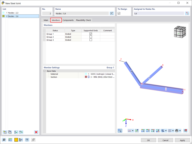
As just described, the members with identical properties are grouped so that you can also see these groupings in the "Members" tab (Image 04). This tab manages the detailed settings of the members connected to the node. Therefore, it is important to provide details for the members, such as their type ("ended" or "continued"). In the “Supported Ends” column you can specify which member should be supported at the remote node in the FE model.
Please note that you can enable supports for multiple members, but at least one member does not have to be supported. The support corresponds to a fixed restraint and should be selected in such a way or at the point that it corresponds most closely to the behavior of the model. For this connection, supported ends are activated for the members of group 1 (that is, member No. 4 and No. 21).
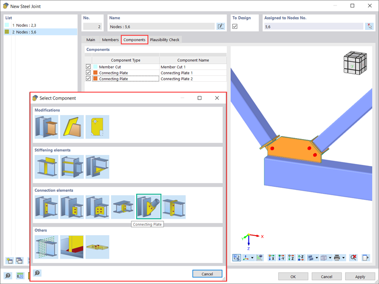
All components of the connection are managed in the Components tab. As already mentioned at the beginning of this text, one of the advantages in RFEM 6 is that steel joints can be created by means of the simple and familiar input of predefined components. Various types of predefined components (e.g., end plate, cleats, fin plates) and universally applicable basic components (plates, welds, auxiliary planes) are available for the input of all types of connection situations.
One of these components is the connecting plate component that is the topic of this article. Thus, in addition to the member cut needed for this connection, two connecting plates are inserted from the library (Image 05). By doing this, all sub-components such as gusset plate, cap plate, tongue plate, welds, and bolts that make up the connecting plate component are available for configuration.
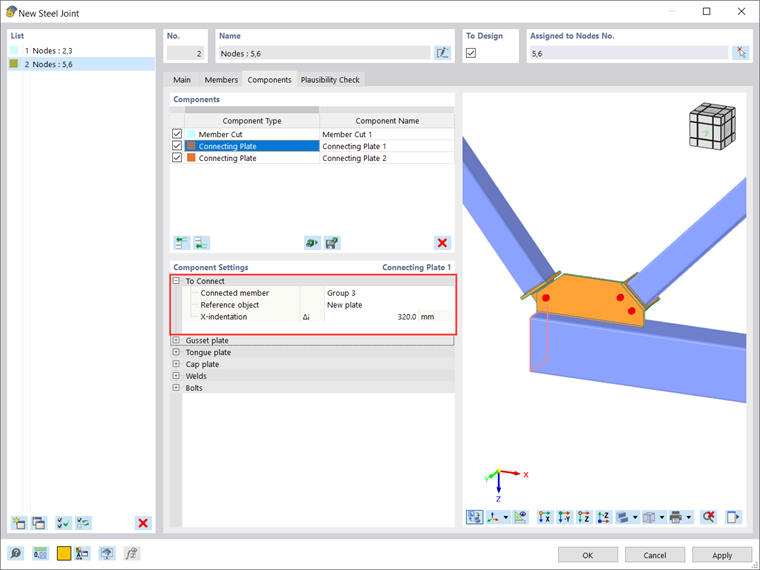
How the settings of a connecting plate are defined is first shown for the settings of connecting plate No. 1. However, before delving into its properties and definition criteria, you need to define the member that is connected by the connecting plate.
You can then choose whether the reference object is an existing object (that is, member, member plate, or existing plate) or a new gusset plate. If, as in this case, you select “New plate” as the reference object (Image 06), the input area for a gusset plate appears. Before configuring it, you can also define the X-indentation, i.e., the distance of the end of the connected member from the theoretical member end.
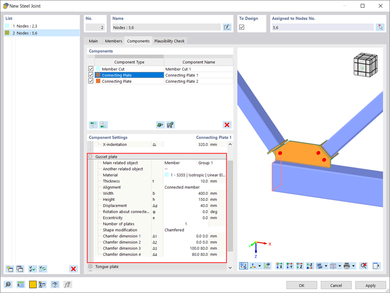
Since "New plate" was selected as the reference object, the input area for a gusset plate appears for configuration (Image 07). The gusset plate is bounded by its main related object, selected in the first row, and can be either a member or a plate (including member plates). It is also possible to define another related object, which is optional if you need to insert the gusset between two existing objects.
Then you need to define the material, thickness, and alignment. In order to select the plane to which the gusset plate will be aligned, you have two options: “Connected member” (aligns the gusset to the XZ plane of the connected member) and “Main related object” (aligns the plate to the plane formed by the longitudinal axes of the main reference object and the connected member). Further parameters that define the gusset plate are its dimensions (that is, width and height), the translation along the longitudinal axis of the associated main object, the rotation about the longitudinal axis of the connected element, the out-of-plane eccentricity of the plate, and the number of plates. The last can be set to 1 or 2; in this case a plate is used. In addition, the gusset can be modified by offsetting, chamfering, or a combination of both. A new definition line appears for each of the changes. For the plate in this case, the gusset is modified with chamfers.
Another sub-component of the connecting plate is the tongue plate. This plate connects the (further defined) cap plate to the reference object and can be viewed as an extension of the connected element in the form of a plate. If the reference object is an existing object, the tongue plate position is adjusted accordingly. If the reference object is a new plate, as in this case, the tongue plate is placed centrically to the connection element, and the position of the new gusset plate is adjusted to the tongue plate.
To define the tongue plate, you must define the material, the dimensions of the plate, and its position. The latter can be selected as front, rear or both. The removed corners of the tongue plate can be modified by chamfering or rounding. For the connection created in this article, the tongue plate is modified with chamfers (Image 08).

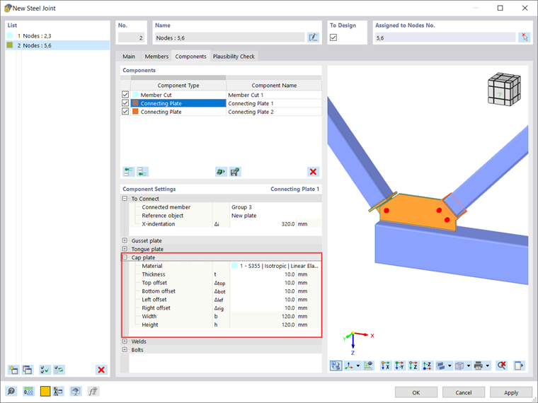
The next subcomponent (that is, the cap plate) can be seen as a connection between the connected element and the tongue plate, the former being welded from one side of the cap plate and the latter being welded from the other site. This plate is defined by the material selection, plate thickness, and the distances to the connected component edges. The overall dimensions of the plate are then automatically displayed in the last two lines of the section (Image 09).
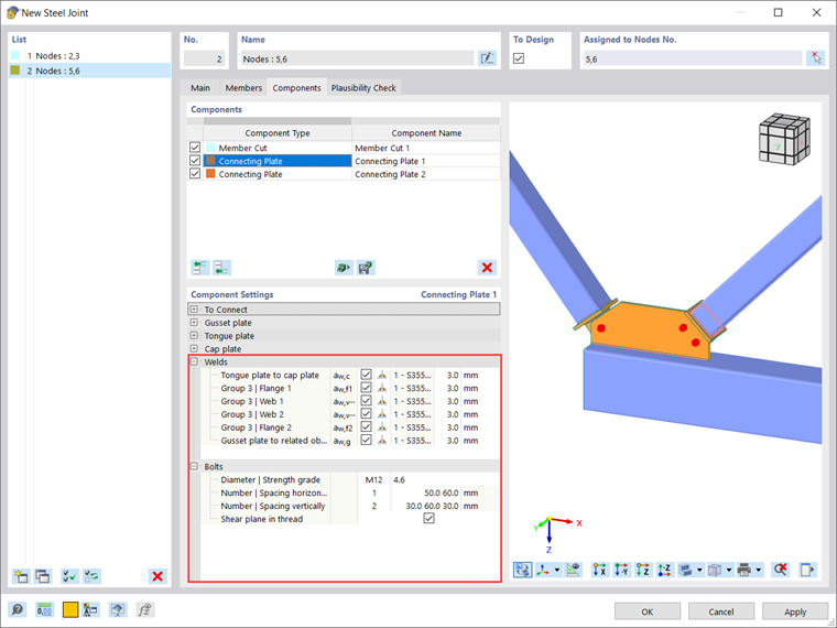
To complete the definition of the connecting plate, you need to specify how all of these new components that are introduced into the connection will be connected. You can do this in the "Welds" and "Bolts" input areas shown in Image 08. The former is placed between the connected element and the cap plate, between the cap plate and the tongue plate, and between the gusset plate and the reference object.
In general, within the above connections, a new definition line is used for each contact between two plates. The definition includes a check box indicating whether to use the weld, the combo box for the weld type, and (for the fillet option) the weld thickness. The bolts, on the other hand, connect the tongue plate and the gusset plate. You will be prompted to define the bolt diameter, bolt class, and bolt properties such as the horizontal and vertical spacing of the bolts.
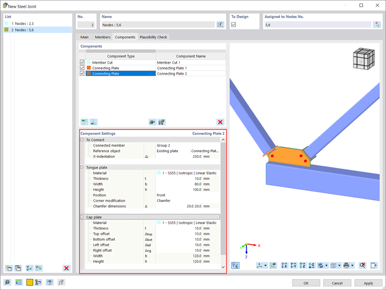
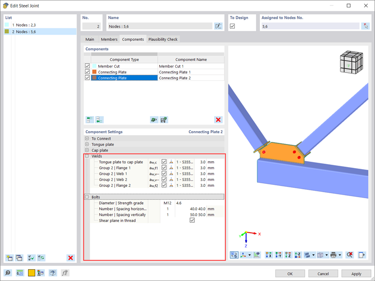
The same should be done for connecting plate No 2. To avoid repeating the whole process and expanding this text, the settings applied are shown in Images 11 and 12.
Finally, the connection defined in this way is shown in Image 13.