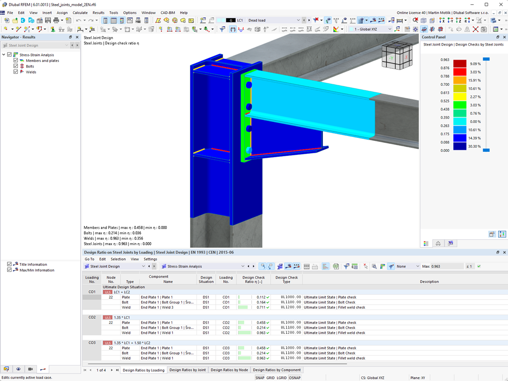
Do you work with steel connections? The Steel Joints add-on for RFEM supports you when analyzing steel connections by using an FE model. In this case, the modeling runs fully automatically in the background. Nevertheless, you can control this process via the simple and familiar input of components. You can then use the loads determined on the FE model for your design of the components according to EN 1993‑1‑8 (including National Annexes).
More About Steel JointsMit der Komponente "Rippe" können Sie sehr schnell eine beliebige Anzahl an Längsrippen an einem Stabblech definieren. Durch die Vorgabe eines Referenzobjektes lassen sich daran automatisch Schweißnähte vorgeben.
Die Komponente "Rippe" lässt sich auch an kreisförmigen Hohlprofilen anordnen. Dafür wird zusätzlich die Vorgabe der Winkel zwischen den Rippen benötigt.
You can now insert a cap plate in steel joints with only a few clicks. You can enter the data using the known definition types "Offsets" or "Dimensions and Position". By specifying a reference member and the cutting plane, it is also possible to omit the Member Section component.
This component allows you to easily model cap plates on column ends, for example.
You can use the "Plate Cut" component to cut plates (for example, gusset plates, fin plates, and so on). There are various cutting methods available:
- Plane: The cut is performed on the closest surface to the reference plate.
- Surface: Only the intersecting parts of plates are cut.
- Bounding Box: The outermost dimension consisting of width and height is cut out of the plate as a rectangle.
- Convex Envelope: The outer hull of the cross-section is used for the plate cut. If there are fillets at the corner nodes of the cross-section, the cut is adapted to them.
In the Steel Joints add-on, you can perform precise cuts on plates and structural components using the "Auxiliary Solid" component. Within this component, you can use the shapes of a box, a cylinder, or any cross-section as a guide object.
Go to Explanatory Video