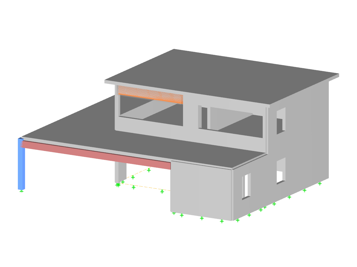
Download the model of a reinforced concrete building here, and open it with the FEA software RFEM.
This model was used for FAQ 4630, among others.
Example of Concrete
Number of Nodes | 84 |
Number of Lines | 83 |
Number of Members | 24 |
Number of Surfaces | 16 |
Number of Load Cases | 6 |
Number of Load Combinations | 18 |
Number of Result Combinations | 2 |
Total Weight | 436.127 tons |
Dimensions (Metric) | 20.335 x 12.835 x 8.170 m |
Dimensions (Imperial) | 66.72 x 42.11 x 26.8 feet |
Program Version | 5.23.02 |
You can download this structural model to use it for training purposes or for your projects. However, we do not assume any guarantee or liability for the accuracy or completeness of the model.
![Setting Wind Direction in Wind Generator](/en/webimage/010475/2981991/01-en.png?mw=512&hash=65e98cfe859ce35a3e3e9da47a0ef9335401520e)
![Generation of Result Beam](/en/webimage/009204/2417579/01-en-png.png?mw=512&hash=e5b08a40fd9a5a16825be6182b3138f78627561e)
![KB 001885 | Assessment of Story Drift under Seismic Loads According to ASCE 7-22 and the Building Model](/en/webimage/051645/3995306/im1.png?mw=512&hash=b8237709c4f30213fac51d86d32a42bddde72f03)
![KB 001883 | Plate Girder Design According to AISC 360-22 in RFEM 6](/en/webimage/051561/3980997/im1.png?mw=512&hash=b8237709c4f30213fac51d86d32a42bddde72f03)
![Activation of Camera Flight Mode in RFEM](/en/webimage/007231/1773731/Kamera-Flugmodus.png?mw=512&hash=bfe40bd5994b64cf3b32c3ec1894bde55d8396b8)
With the Camera Fly Mode view option, you can fly through your RFEM and RSTAB structure. Control the direction and speed of the flight with your keyboard. Additionally, you can save the flight through your structure as a video.
![Defining Load Eccentricity for Uniform Member Load](/en/webimage/006848/1585470/1-en-us-png.png?mw=512&hash=5b100bb1bdececb35d942f4f843827e0bc899c6f)
You can define eccentricities for member loads of the load type 'Force'. You can apply the load eccentricities by means of an absolute or relative offset.
We recommend using the large deformation analysis to consider all effects of eccentric loads.
![Add-on "Steel Joints for RFEM 6" | Component Library](/en/webimage/043097/3898884/steel_joints_components.png?mw=512&hash=e4f835906155863fc7019d5043b22e553dc766f9)
- Numerous component types, such as base and end plates, web angles, fin plates, gusset plates, stiffeners, tapers, or ribs for easy input of typical connection situations
- Universally applicable basic components (such as plates, welds, bolts, auxiliary planes) for modeling complex connection situations
- Graphical display of the connection geometry with dynamic updating during the input
- Wide range of cross-section shapes: I-sections, U-sections, angles, T-sections, hollow sections, built-up cross-sections and thin-walled sections
- Library in Dlubal Center with program template connections as well as user-defined templates
- Automatic adaptation of the connection geometry based on the relative arrangement of the components to each other – even in case of subsequent editing of the structural components
![Feature 002828 | Fire Design of Slabs and Walls According to Simplified Table Method](/en/webimage/050837/3925042/50837.png?mw=512&hash=b06639a36ab8b62ab6d08e08552a5ec274469a37)
In the Concrete Design add-on for RFEM 6, you can perform the fire design of reinforced concrete slabs and walls according to the simplified table method (EN 1992‑1‑2, Section 5.4.2 and Tables 5.8 and 5.9).