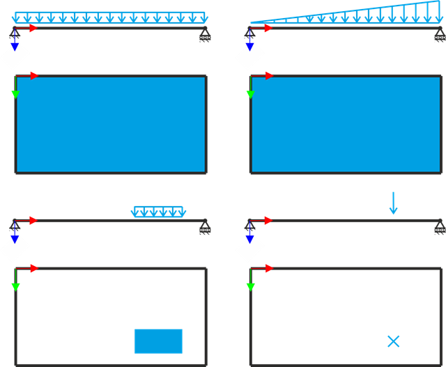
A simply supported rectangular plate is subjected to different load types. Assuming only the small deformation theory and neglecting self-weight, determine the deflection at its centroid for each load type.
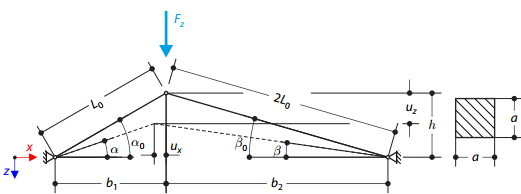
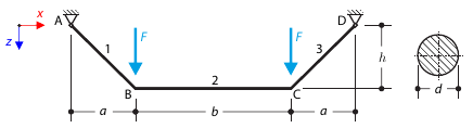
A structure is made of two trusses of unequal length, which are embedded into the hinge supports. The structure is loaded by concentrated force. The self-weight is neglected. Determine the relationship between the loading force and the deflection, considering large deformations.
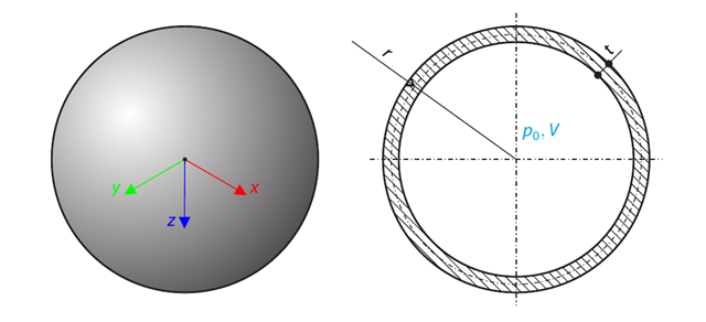
A spherical balloon membrane is filled with gas with atmospheric pressure and defined volume (these values are used for FE model definition only). Determine the overpressure inside the balloon due to the given isotropic membrane prestress. The add-on module RF-FORM-FINDING is used for this purpose. Elastic deformations are neglected both in RF-FORM-FINDING and in the analytical solution; self-weight is also neglected in this example.
Determine the allowable axial compressive strength of a pinned 8-foot-long beam of various cross-sections made of Alloy 6061-T6 and laterally restrained to prevent buckling about its weak axis in accordance with the 2020 Aluminum Design Manual.
Verify that a beam of different cross-sections made of Alloy 6061-T6 is adequate for the required load, in accordance with the 2020 Aluminum Design Manual.
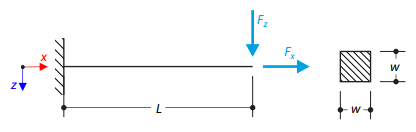
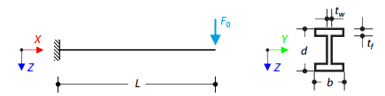
A cantilever is loaded by a transversal and an axial force on the right end and is fully fixed on the left end. The problem is described by the following set of parameters. The problem is solved by using the geometrically linear analysis, second-order analysis, and large deformation analysis.
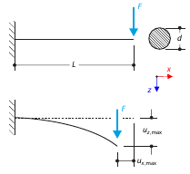
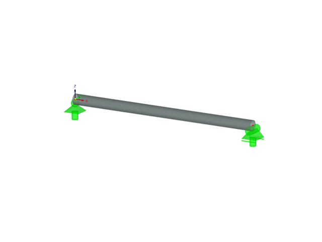
A console is loaded by concentrated force at its free end. Determine the maximum deflection of the console using large deformation analysis.
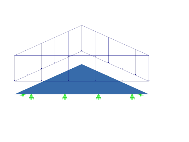
A simply supported equilateral triangular plate is subjected to a uniformly distributed transverse load. Assuming the small deformation theory and neglecting self‑weight, the maximum out‑of‑plane deflection of the plate is determined.
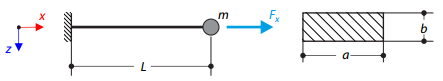
A cantilever of rectangular cross‑section has a mass at the end. Furthermore, it is loaded by an axial force. Calculate the natural frequency of the structure. Neglect the self‑weight of the cantilever and consider the influence of the axial force for the stiffness modification.
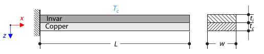
A bimetallic strip is composed of invar and copper. The left end of the bimetallic strip is fixed, and the right end is free, loaded by temperature difference. While neglecting self-weight, determine the deflection of the bimetallic strip (free end).

A column is composed of a concrete section (rectangle 100/200) and a steel section (profile I 200). It is subjected to pressure force. Determine the critical load and corresponding load factor. The theoretical solution is based on the buckling of a simple beam. In this case, two regions have to be taken into account due to different moments of inertia and material properties.
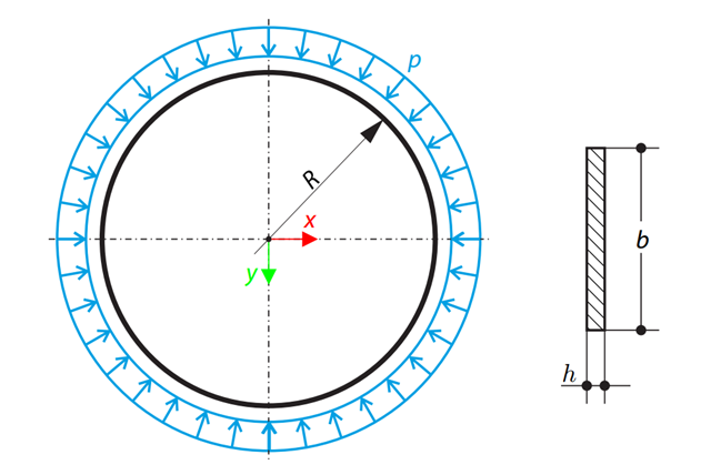
A thin circular ring of a rectangular cross-section is exposed to external pressure. Determine the critical load and corresponding load factor for in-plane buckling.
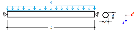
A steel cable or membrane with pins on both ends is loaded by distributed loading. Neglecting its self-weight, determine the maximum deflection of the structure using the large deformation analysis.
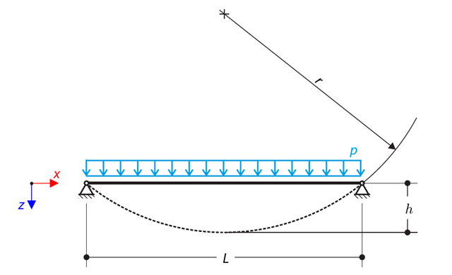
A cable is loaded by means of a uniform load. This causes the deformed shape in the form of the circular segment. Determine the equilibrium force of the cable to obtain the given sag of the cable. The add-on module RF-FORM-FINDING is used for this purpose. Elastic deformations are neglected both in RF-FORM-FINDING and in the analytical solution; self-weight is also neglected in this example.
A cable in the initial position is loaded by two concentrated forces. The self‑weight is neglected. Determine the normal forces in the cable.
Time history analysis of a cantilever beam (SDOF system) excited by a periodic function. Vertical deformations and accelerations calculated with direct integration and modal analysis in RF‑/DYNAM Pro - Forced Vibrations are compared with the analytical solution.
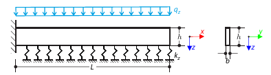
A cantilever from a rectangular cross-section is lying on an elastic Pasternak foundation and loaded by distributed loading. The image shows the calculation of the maximum deflection and maximum bending moment.

A cantilever from a rectangular cross-section is lying on an elastic Winkler foundation and loaded by distributed loading. The image shows the calculation of the maximum deflection and maximum bending moment.
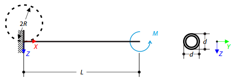
Determine the bending moment which, acting at the free end of the cantilever, will bend the member into a circular shape. Neglecting the beam's self-weight, assuming the large deformation analysis, and loading the cantilever with the moment, determine its maximum deflections.
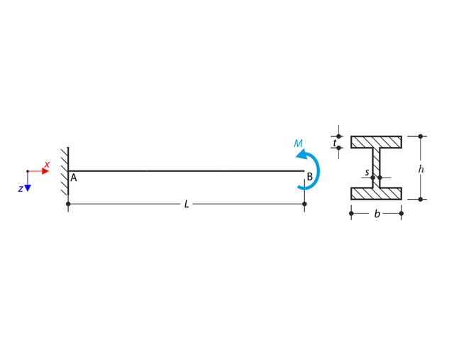
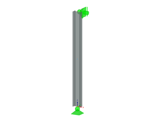
An I-profile cantilever is supported on the left end and loaded by torque. The aim of this example is to compare the fixed support with the fork support and to investigate the behavior of some representative quantities. Comparison is also made to the solution by means of plates. Small deformations are considered, and the self-weight is neglected. Determine the rotation in the midpoint of the cantilever, and in case of the member entity with warping, determine the values of the primary torsional moment, the secondary torsional moment, and the warping moment both on the left end (point A) and the right end (point B).