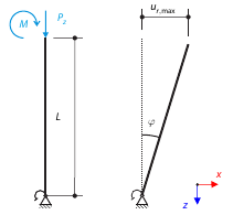
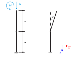
Consider a rigid scaffolding tube, fixed at the bottom using the Scaffolding Nodal Support and loaded by both a moment and a force. Calculate the maximum deflection with consideration of initial slippage.
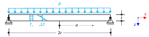
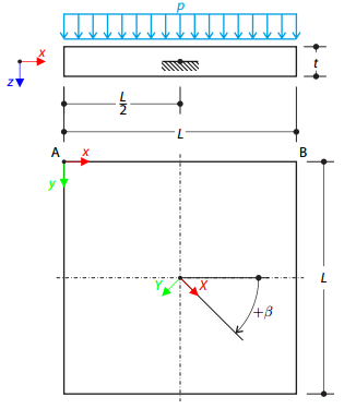
Determine the maximum deflection and maximum radial moment of a simply supported circular plate subjected to uniform pressure, uniform temperature, and differential temperature.
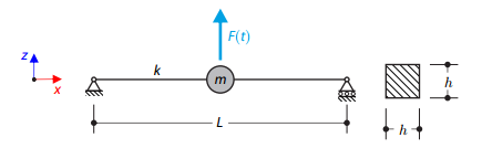
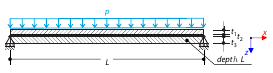
A long, thin beam is carrying a concentrated mass and is loaded by a time-dependent force. It is simply supported. The problem is described using the following parameters. Determine the deflections in the given test times.
Consider a rigid scaffolding tube, fixed at the bottom using the Scaffolding Nodal Support and loaded by both a moment and a force. Calculate the maximum radial deflection by exceeding the capacity of the scaffolding support.
One layered square orthotropic plate is fully fixed at its middle point and subjected to pressure. Compare the deflections of the plate corners to check the correctness of the transformation.
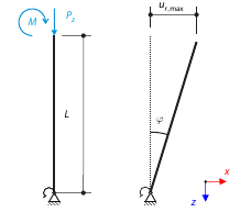
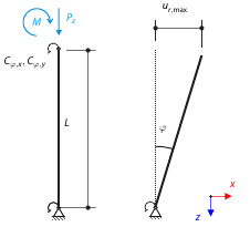
Consider a rigid scaffolding tube, fixed at the bottom using the Scaffolding Nodal Support and loaded by both a moment and a force. Self-weight is not considered. Considering an infinitely rigid beam, determine the maximum radial deflection.
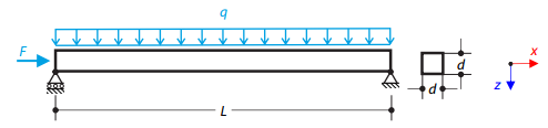
A steel beam with a square cross-section is loaded with an axial force and distributed loading. The image shows the calculation of the maximum bending deflection and critical load factor according to the second-order analysis.
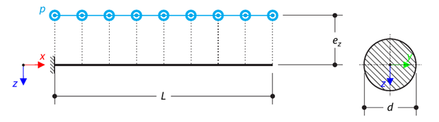
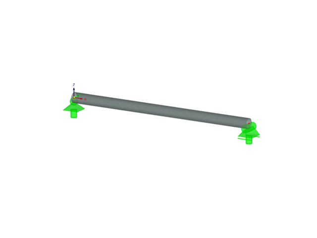
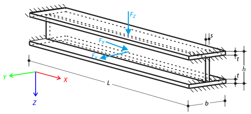
A console made of a round bar is loaded by an eccentric uniform load. Determine the maximum deflection and maximum twist of the console using the geometrically linear analysis.
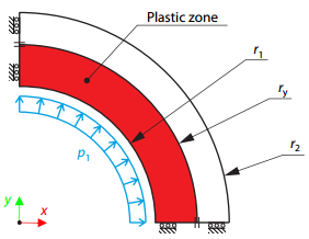
A thick-walled vessel is loaded by an inner pressure such that the vessel reaches an elastic-plastic state. While neglecting self‑weight, the analytical and numerical solutions for the radial position of the plastic zone border (under the Tresca hypothesis) are determined and compared.
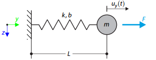
A single mass system is subjected to loading force. Determine the deflection of the system.
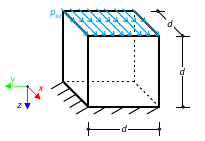
Determine the maximum deflection of a cube. The cube's lower side is fully fixed and the upper side is subjected to shear loading.
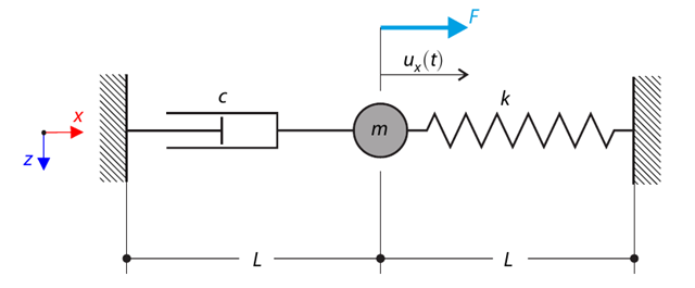
A single-mass system with dashpot is subjected to a constant loading force. Determine the spring force, damping force, and inertial force at the given test time. In this verification example, the Kelvin--Voigt dashpot (namely, a spring and a damper element in serial connection) is decomposed into its purely viscous and purely elastic parts, in order to better evaluate the reaction forces.
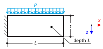
Determine the maximum deflections of the block while considering or neglecting shear effect. The square block of the isotropic material is fully fixed at one end and loaded with uniform vertical pressure.
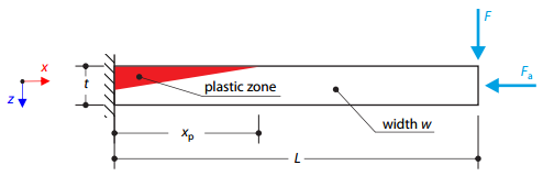
A cantilever is fully fixed on the left end and loaded by a transverse force and an axial force on the right end. The tensile strength is zero and the behavior in the compression remains elastic.
Determine the maximum deflection and stress in the z-direction of the composite plate, consisting of two glass layers and one foil layer in between, subjected to uniform pressure.
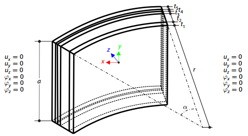
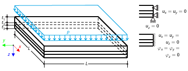
A composite plate consisting of three glass layers, one foil layer, and an inner space with dry air, is fully fixed and loaded with a variable temperature. Neglecting its self-weight, determine the plate's maximum deflection.
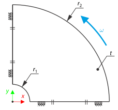
A compact disc (CD) rotates at a speed of 10,000 rpm. Therefore, it is subjected to centrifugal force. The problem is modeled as a quarter model. Determine the tangential stress on the inner and outer diameters and the radial deflection of the outer radius.
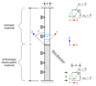
Determine the maximum deflection of a three-dimensional block fixed at both ends. The block is divided in the middle: the upper half is made of an elastic material and the lower part is made of timber - an elasto-plastic othotropic material with the yield surface described according to the Tsai-Wu plasticity theory. The block's middle plane is subjected to vertical pressure.
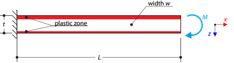
A cantilever is fully fixed on the left end and loaded by a bending moment on the right end. The material has different plastic strengths under tension and compression.
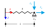
The goal of this example is to demonstrate an irreversible process caused by friction. After the loading and unloading, the end-point is in a different position than where it was at the beginning. Determine the movement of the node in the X direction.
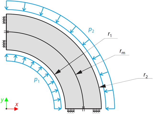
A two-layered, open-ended, thick-walled vessel is loaded by inner and outer pressure; therefore, there is no axial stress. While neglecting self‑weight, the radial deflection of the inner and outer radius, and the pressure (radial stress) in the middle radius is determined.
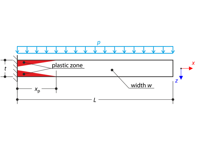
A thin plate is fully fixed on the left end and loaded by uniform pressure. Plastic material is considered for the calculation.
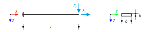
Prove that coupling different dimensional elements does not affect the results. A cantilever with a rectangular cross-section is fixed at one end and loaded at the other by concentrated forces. Neglecting its self-weight and assuming only small deformations, determine the cantilever's maximum deflections.
Consider a scaffolding tube connection subjected to an axial force and a moment. Self-weight is not considered. The material of the tube is idealized as perfectly rigid. All geometrical non-linearities are ignored. Determine the angle of deflection.
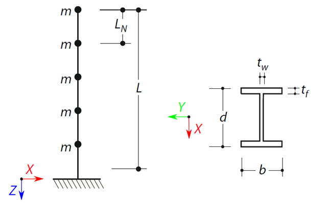
A cantilever beam with an I-beam cross-section of length L is defined. The beam has five mass points with masses m acting in the X-direction. The self-weight is neglected. The frequencies, mode shapes, and equivalent loads of this 5-DOF system are analytically calculated and compared with the results from RSTAB and RFEM.
Determine the maximum displacement, in-plane stresses, and stress ratios of a simply supported double-pane glass plate with a foil between both glass panes subjected to uniform pressure.
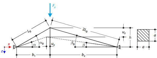
A structure is made of two trusses of unequal length, which are embedded into the hinge supports. The structure is loaded by concentrated force. The self-weight is neglected. Determine the relationship between the loading force and the deflection, considering large deformations.
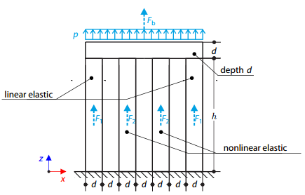
Four columns are fixed at the bottom and connected by a rigid block at the top. The block is loaded by pressure and modeled by an elastic material with a high modulus of elasticity. The outer columns are modeled by linear elastic material and the inner columns by a stress-strain diagram with decaying dependence. Assuming only the small deformation theory and neglecting the structure's self-weight, determine its maximum deflection.
Verify that a beam of different cross-sections made of Alloy 6061-T6 is adequate for the required load, in accordance with the 2020 Aluminum Design Manual.
One layered square orthotropic plate is fully fixed at its middle point and subjected to pressure. Compare the deflections of the plate corners to check the correctness of the transformation.