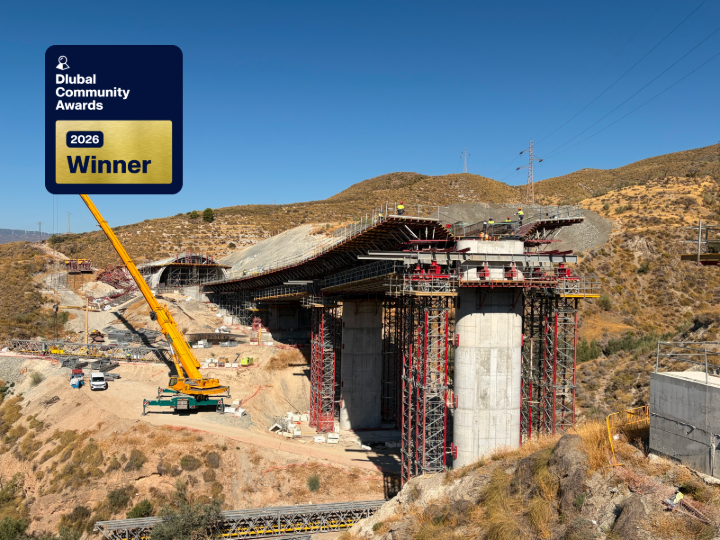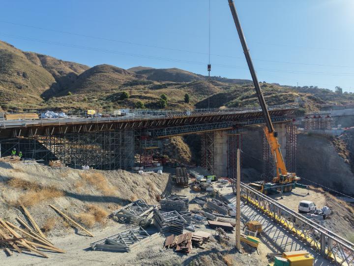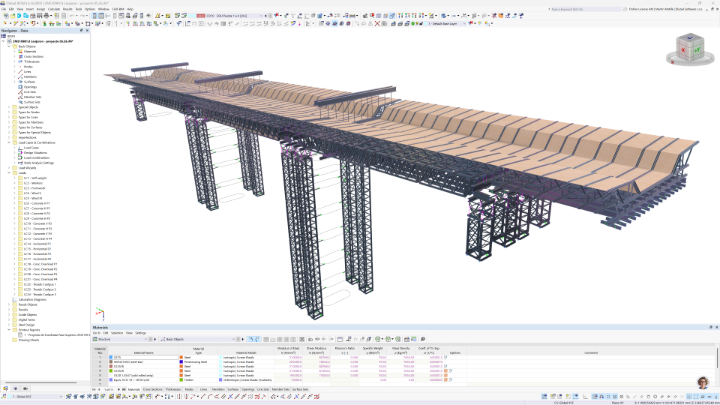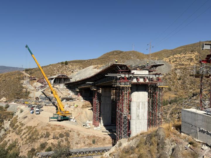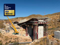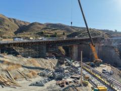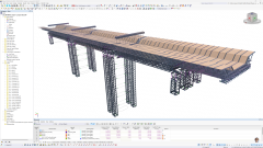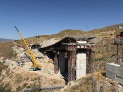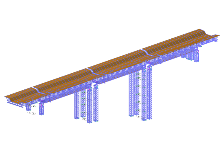
The cast-in-place concrete deck was constructed in four pours, with each pour covering approximately one span plus one-fifth of the next span. The temporary works combine steel trusses, temporary towers, and a modular formwork system, whose configuration and load path evolve throughout the construction sequence.
A key feature of the design is the integration of the temporary structure with the concreting sequence, ensuring that the system remains efficient and stable while accommodating the changing geometry and loading conditions.
The temporary works are predominantly made of steel, with several steel grades used according to the requirements of each component. The most demanding elements are approximately 35-m (115-ft) span steel trusses and slender temporary towers exceeding 25 m (82 ft) in height, with a footprint of approximately 1.5 m × 1.5 m (5 ft × 5 ft).
Before the concrete deck becomes self-supporting, the temporary works need to support a total service load of about 350 kN/m (258 kip/ft) of total load, including fresh concrete, formwork self-weight, and construction loads. The main engineering challenge was therefore to support this substantial load over large spans with a limited number of trusses that could be practically installed beneath the deck.
To increase the efficiency of the available temporary steelwork, hangers were tensioned at approximately one-fifth points of the spans, and their effect was evaluated throughout the relevant construction stages.
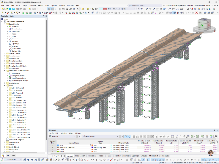
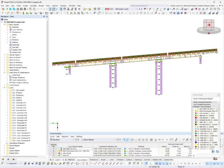
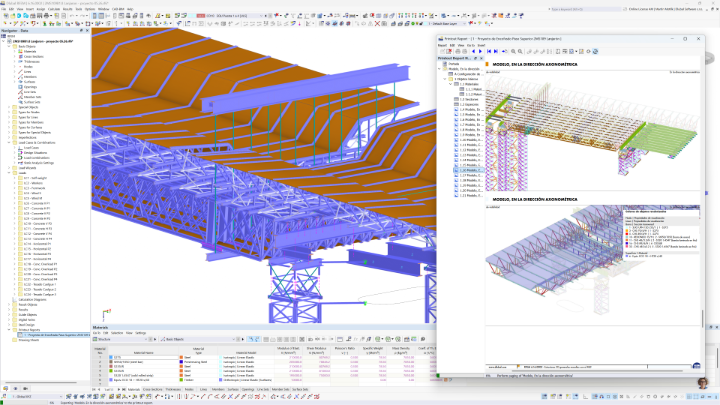
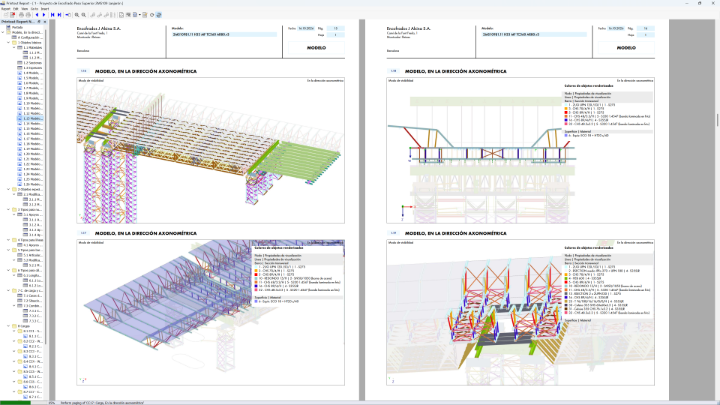
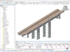
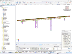
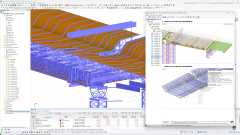
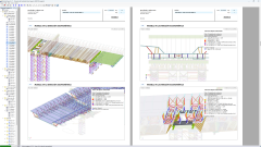
Dlubal RFEM 6 was used for the global three-dimensional analysis of the main temporary works. The model contains more than 38,000 members and their corresponding hinges, representing the complete temporary structure and its changing configuration during construction.
Several steel grades were considered, and the corresponding resistance checks were performed using the Steel Design add-on. Different ultimate configurations were assigned to the members according to their cross-section typology and specific buckling conditions. This allowed for the design assumptions to be adapted to the behavior of each type of steel member. Complex and non-standard cross-sections were generated using RSECTION and incorporated into the RFEM model.
The four concreting stages were reproduced using structure modifications to activate or deactivate groups of members, supports, and other structural objects according to the progress of the works. Furthermore, member stiffness modifications were used to modify the structural behavior and force transmission between members for each construction stage.
The model also incorporated the tensioning of the hangers at approximately one-fifth points of the spans, enabling the evaluation of its effect on load redistribution and the efficiency of the temporary structure throughout the relevant phases.
Control of assembly and deformation was also crutial. The trusses were assembled on the ground and then lifted into position. RFEM predicted vertical displacements exceeding 10 cm (3.9 in) at the centers of the largest spans. These results were used to define the required precambering of the trusses for assembly, which linked the structural analysis directly to the construction process. Thus, the model provided both structural design and essential information for the practical execution of the temporary works.
At the time of submission, the construction works are ongoing, with completion expected by the end of 2026. The temporary works system has already been installed and operated successfully during the initial concreting stages.
The behavior observed on site is consistent with the RFEM predictions. Measured vertical deformations show good agreement with the calculated values. This provides practical validation of the structural model and its assumptions.
The successful performance of the system highlights the essential role of advanced structural analysis software like RFEM in modern construction, enabling accurate design, optimization, and safe execution of complex temporary works.
| Location | A-348 Lanjarón viaduct in Granada, Spain. |
| Client | Junta de Andalucía - Ministry of Development, Territorial Planning and Housing |
| Main Contractor | UTE Lanjarón |
| Formwork | Alsina Formwork |