


Topic:
Design of K-Type Joint Using CHS-Sections According to EN 1993-1-8
Annotation:
Closed circular cross-sections are ideal for welded truss structures. The architecture of such structures is popular when designing transparent roofs. This article shows the special features of the connection design using hollow sections.
Description:
General
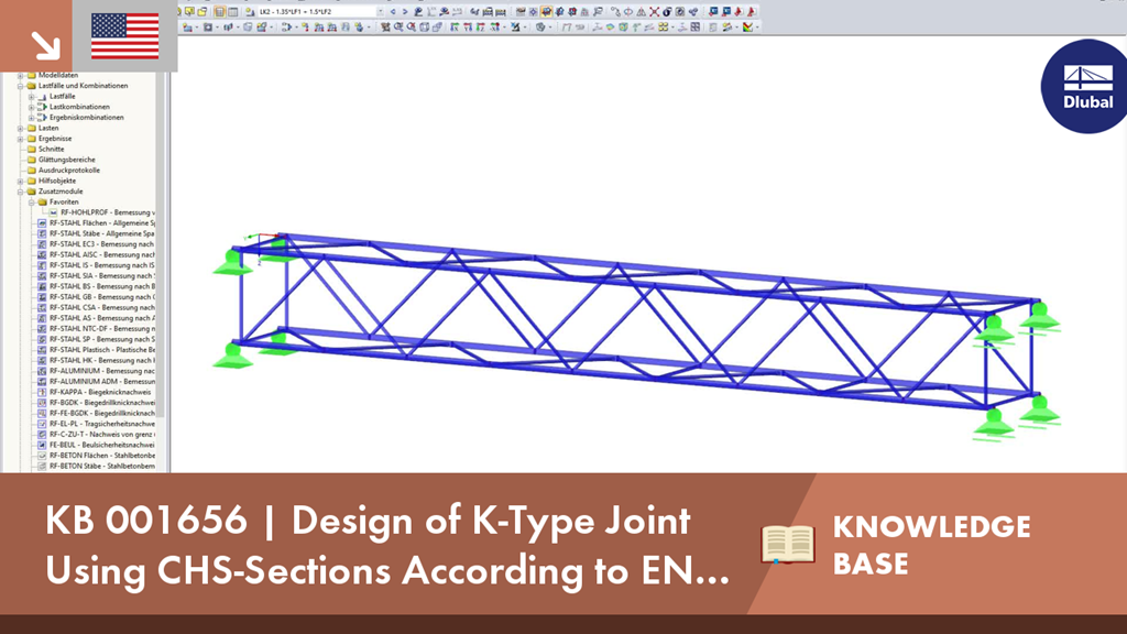
Slender truss structures made of closed cross-sections are popular in architecture. Due to the computer-aided production of cuts and connection geometries, complex spatial nodes are also possible. This technical article deals with the design of a K‑node. Especially the node definition and the design are described in detail.
Details of Model
Material: S355
Chord cross-section: RO 108x6.3 | DIN 2448, DIN 2458
Strut cross-section: RO 60.3x4 | DIN 2448, DIN 2458
Dimensions: see the graphic
Assigning Node to Joint Type
The connection type for a hollow section node is not only defined by the geometry, but also by the orientation of the axial forces in the struts. In our example, there is a tensile force in Member 35 (Strut 1) and a compression force in Member 36 (Strut 2) on Node 28 to be designed. Given this distribution of internal forces and moments, the joint type is a K‑node. If there was compression or tension in both struts, the connection type would be a Y‑node.
Checking Validity Limits
Compliance with the validity limits is crucial for any design. The ratio of the diameters of struts and chords is important. If it is not in the range of 0.2 ≤ d-i / d-o ≤ 1.0, the design cannot be performed. The diameter ratio d-i / d-o is also referred to as β. The European standard EN 1993‑1‑8 [1] specifies in Table 7.1 the validity limits for struts, chord members as well as a limitation of the struts' overlap. If you want to have a gap between the struts, a minimum dimension of g ≥ t-1 + t-2 must be observed, too. t is the respective wall thickness of the struts. Structural components subjected to compression also need to be classified into cross-section classes 1 or 2. A corresponding check is carried out according to EN 1993‑1‑1 [2], Section 5.5.
Design Process
In our example, the connection meets the validity limits according to Table 7.1. Therefore, it is sufficient according to EN 1993‑1‑8, Section 7.4.1 (2), to analyze the chord member for flange failure and punching shear.
Flange failure of chord member due to axial force according to EN 1993‑1‑8, Table 7.2, row 3.2:
Determination of diameter-wall ratio γ
γ = 8.57
Determination of factor k-g
k-g = 1.72
Determination of chord tension coefficient k-p
f-p is the chord tension from the initial axial force N-p and the additional moment from eccentricity. Since there is compression and tension in the chord, it is assumed that N-p = 0. Furthermore, the eccentricity of the joint is so small that an additional moment from any eccentric connection of the struts does not have to be considered. Thus, the auxiliary factor f-p is zero. The sign convention for compression and tension forces in RFEM and RSTAB differs from those of the European standard EN 1993‑1‑8. Therefore, the formula for k-p has been adjusted.
k-p = 1.0
Determination of allowable limit internal force N-Rd
N-1,Rd = N-2,Rd = 257.36 kN
N-1,Ed / N-1,Rd = 197.56 / 257.36 = 0.77