Question:
I would like to model a frame beam with a tapered cross-section. For this, I have created a member with the cross-section distribution "Tapered at member start". However, the resulting cross-section is displayed incorrectly in the rendering. What is the problem here?
Answer:
If there are different cross-section types at the start and end of a tapered member that do not have the same number of stress points, RFEM/RSTAB draws the first half with one cross-section and the second half with the other cross-section.
Furthermore, it is necessary to ensure that the stress points with the same numbers are opposite each other.
Generally, the cross-sections defined in RSECTION 1 cannot be used to create tapers.
Image 01 shows the result of a cross-section pairing with a different number of stress points.
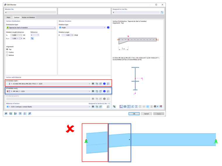
This also applies if a member is tapered at the member start. The stress points of the cross-sections used must match each other over the entire member length.
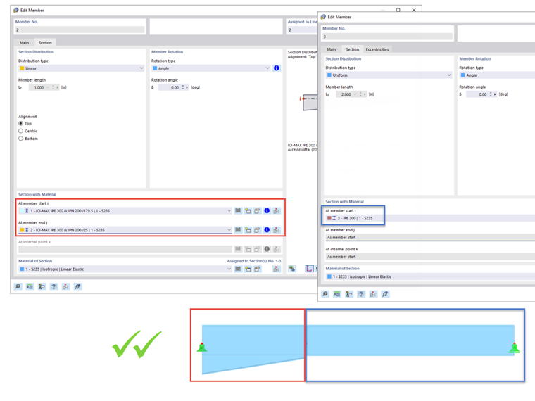
In Image 02, the taper at the member start is entered correctly.
Trying to generate the cross-section transition to the rest of the member by using another taper leads to an incorrect member definition.
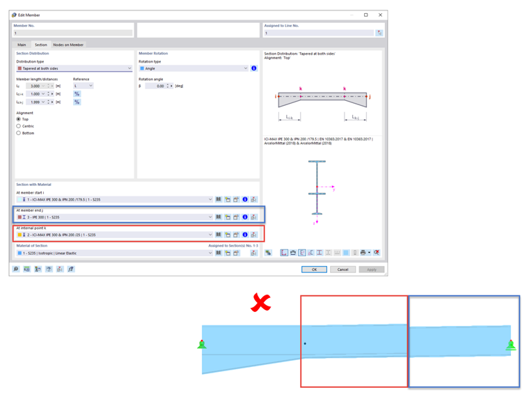
Image 03 shows an option for defining the cross-section. In this case, however, the coupled cross-section of the taper goes to the end of the entire member.
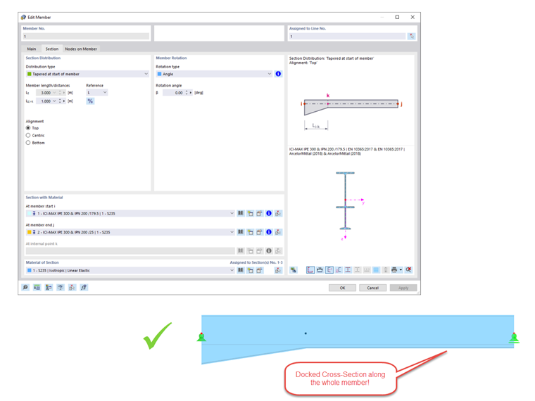
If it is absolutely necessary that the rest of the member has a different cross-section than the taper at the member start, it is necessary to divide the member. This way, you can display the taper (taking into account the arrangement of the stress points) as a member with the "Linear" cross-section distribution and select any other cross-section for the rest of the member. This is shown in Image 04.