


Topic:
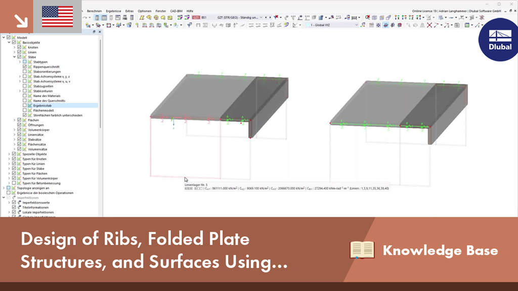
Design of Ribs, Folded Plate Structures, and Surfaces Using Result Members in RFEM 6
Note:
If, for example, you want to use a pure surface model to determine the internal forces, but you still want to design a component using the member model, you can do this using the result beam.
Description:
The result beam allows you, for example, to integrate surface internal forces along the member axis within a defined area and then design them.
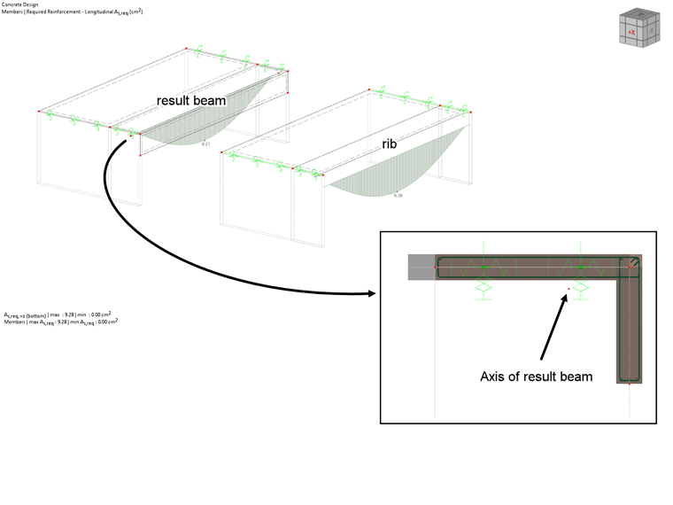
Design
These internal forces and the cross‑section assigned to the result beam are used for the design. It is very important that the axis of the result beam runs through the centroid of the cross-section under consideration, as the internal forces are integrated taking the respective lever arm into account.
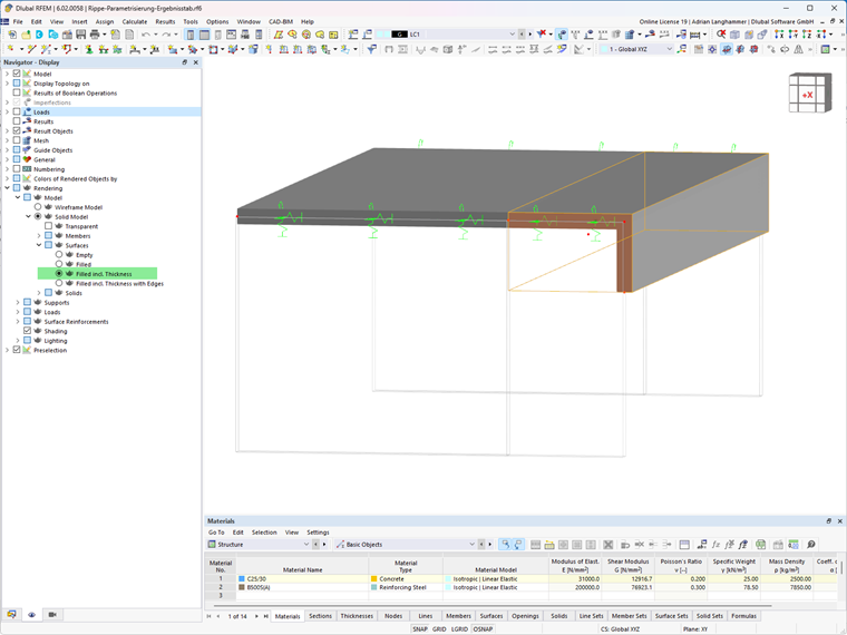
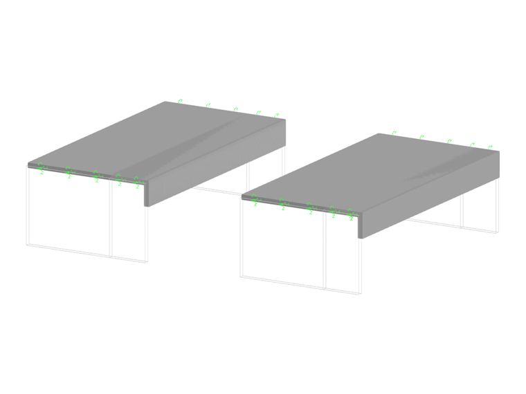
Graphical Check
You can use the rendered view to graphically check whether the result beam is correctly arranged. In this context, the surfaces must be represented including their thickness. The edges of the result beam's cross-section must match the edges of the surfaces displayed.
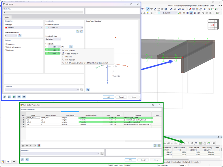
Parametrization
Here, the parametrization is only an extended option for input. It is, of course, not necessary when using the result table.
However, if, for example, the cross-section of a T-beam needs to be varied frequently during the modeling of a downstand beam, the position of the result beam axis can be entered using parameters. If you define the position of the axis depending on the cross-section parameters of the result beam, you only need to change the cross-section. The axis of the result beam is then aligned automatically.
More Videos:
► KB 001838 | Design of Ribs, Folded Plate Structures, and Surfaces Using Result Members in RFEM 6: https://www.youtube.com/watch?v=ZfjqiVw-rOE