


Subject:
AISC 341 Braced Frame Design in RFEM 6
Comment:
The design of an Ordinary Concentrically Braced Frame (OCBF) and a Special Concentrically Braced Frame (SCBF) can be carried out in the Steel Design add-on of RFEM 6. The seismic design result according to AISC 341-16 and 341-22 is categorized into two sections: Member Requirements and Connection Requirements.
Description:
More in-depth details on the Seismic Configuration input are covered in the article
KB | AISC 341 Seismic Design in RFEM 6
.
Member Requirements
The following design checks for members that are part of the seismic force-resisting system (SFRS) are available in RFEM. The sections listed refer to Seismic Provisions AISC 341-16/22 [1].
- Width-to-Thickness Limitations [Section D1.1 and F1.5a]
- SCBF Stability Bracing of Beams - Required Strength & Stiffness [Sections F2.4b and D1.2a.1(b)]
- SCBF Stability Bracing of Beams - Maximum Spacing [Sections F2.4b and D1.2a.1(c)]
- Column Required Strength [Section D1.4a]
- Brace Slenderness Ratio [Section F1.5b for OCBF and F2.5b(a) for SCBF]
Width-to-Thickness Limitations for Ductility Requirements
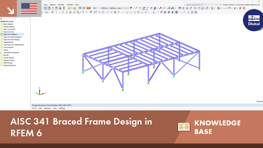
The braces in OCBF are designated as moderately ductile members according to Section F1.5a. All members (braces, beams, columns) in SCBF are designated as highly ductile members according to Section F2.5a.
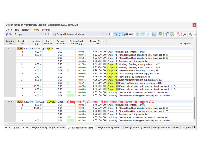
The braces in OCBF must satisfy the requirements of AISC Seismic Provisions Section D1.1 for moderately ductile members. As an exception according to Section F1.5a, braces in tension-only frames with L-c/r greater than 200 do not need to satisfy the ductility requirement. This design check is shown as EQ 1300 in RFEM (Image 1).
Note: Tension-only frames are not permitted in SCBF as per Section F2.4d.
Stability Bracing of Beams in SCBF
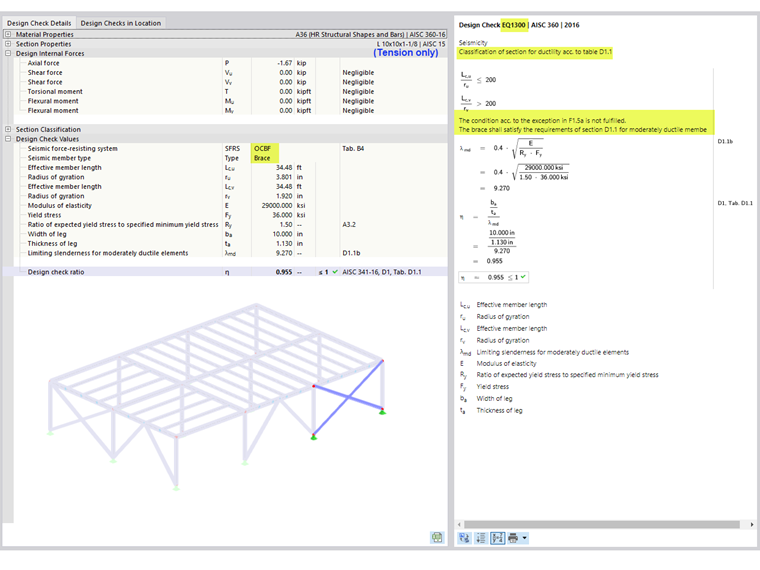
The requirement for stability bracing is only applicable for beams in V- and inverted V-braced frames as per Section F2.4b [1]. The required strength and stiffness of the stability bracings are listed in the Stability Bracing by Member tab under “Seismic Requirements” (Image 2). These values can be compared to the calculated available strength and stiffness when designing the bracing members that frame into the beam. There are no design check details available (only references).
The required strength, Pbr, is defined in Equation A-6-7 of Appendix 6 of AISC 360-16/22 [3]:
|
Pbr |
Required strength of the stability beam bracing |
|
Mr |
Required flexural strength of the beam. Mr = RyFyZ/αs [AISC 341 Equation D1-1] |
|
Cd |
Double curvature factor = 1.0 [AISC 341 Section D1.2a(b)] |
|
ho |
Distance between the flange centroid ho = d - tf |
Note: Pr is not applicable to braced frames.
The required stiffness, βbr, is defined in Equation A-6-8 of Appendix 6 of AISC 360-16/22 [3]:
|
βbr |
Required stiffness of the stability beam bracing |
|
Mr |
Required flexural strength of the beam |
|
Cd |
Double curvature factor = 1.0 |
|
Lbr |
Maximum spacing of the stability beam bracing |
|
ho |
Distance between the flange centroid |
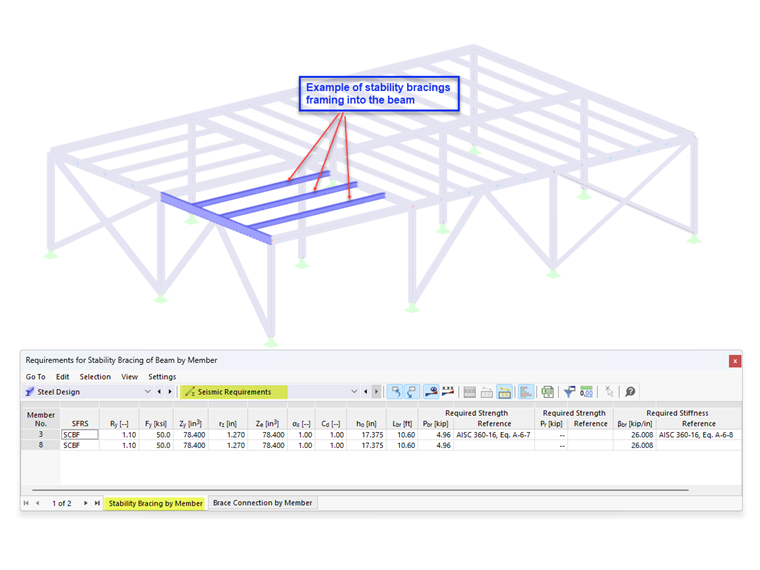
The maximum spacing of the stability bracing must satisfy the requirements of AISC 341-16/22 Section F2.4b, which refers to Section D1.2a.1(c):
|
Lbr |
Maximum spacing of the stability beam bracing |
|
ry |
Radius of gyration about the weak axis |
|
E |
Modulus of elasticity |
|
Ry |
Ratio of the expected yield stress to the specified minimum yield stress |
|
Fy |
Specified minimum yield stress |
The design check for the maximum spacing is presented together with the other member requirements in the Design Ratios on Members. The braced length, Lb, is the specified effective length for lateral-torsional buckling (LTB). The design check detail is shown in EQ 2100 (Image 3).
Column Required Strength
All columns that are part of the seismic force-resisting system (SFRS) are required to be designed with overstrength loads. In many cases, the amplified axial force does not need to be combined with the concurrent bending moments. The option to neglect all bending moments, shear, and torsion in columns for overstrength limit state is activated by default. This option can be deactivated in the Seismic Configuration.
For standard load combinations without overstrength from seismic load effect, the combined loading is checked according to AISC 360-16/22 Chapter H.
For load combinations with overstrength seismic load, Chapter H is not applied when the option to neglect all bending moments, shear, and torsion in columns for overstrength limit state is activated. Example 4.3.2 of the Seismic Design Manual [2] demonstrates the design using the controlling case from both load combinations, standard and overstrength.
Bending moments resulting from a load applied between points of lateral support can contribute to column buckling. Therefore, they are required to be considered concurrently with the axial loads by deactivating the option to neglect the moments (Image 4).
Brace Slenderness Ratio
For braces in V or Inverted V Frames in OCBF, the slenderness ratio L-c/r must be less than or equal to 4*√(E/F-y) according to Section F1.5b [1]. The intent is to limit the unbalanced forces that develop in framing members after brace buckling. This design check is shown as EQ 3300 in RFEM (Image 5).
For braces in X-configuration, the option to meet this requirement can be deactivated in the Seismic Configuration.
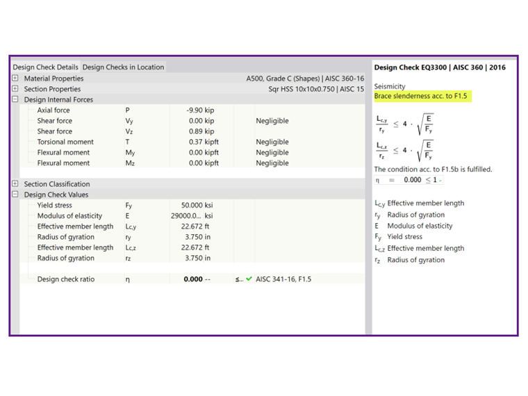
For braces in SCBF, the slenderness ratio L-c/r must be less than or equal to 200, according to Section F2.5b(a) [1]. This design check is shown as EQ 3310 in RFEM ...