Answer:
RSTAB 8 is pure frame analysis software and only determines internal forces, deformations, and support reactions.
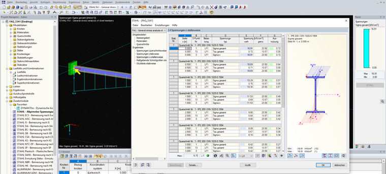
On the other hand, stresses are variable depending on the cross-section, and are calculated on the stress points of a cross-section. This stress determination is performed in the RF-/STEEL add-on module by calculating the existing stresses and comparing them to the limit stresses.