' get model interface Set iApp = iModel.GetApplication() iApp.LockLicense ' get calculation interface Dim iCalc As RFEM5.ICalculation2 Set iCalc = iModel.GetCalculation 
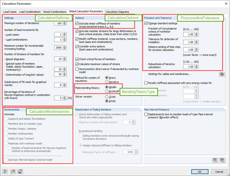
' get surface bending theory Dim calc_bend As RFEM5.BendingTheoryType calc_bend = iCalc.GetBendingTheory ' get settings for nonlinearities Dim calc_nl As RFEM5.CalculationNonlinearities calc_nl = iCalc.GetNonlinearities ' get precision and tolerance settings Dim calc_prec As RFEM5.PrecisionAndTolerance calc_prec = iCalc.GetPrecisionAndTolerance ' get calculation settings Dim calc_sets As RFEM5.CalculationSettings calc_sets = iCalc.GetSettings ' get calculation options Dim calc_opts As RFEM5.CalculationOptions calc_opts = iCalc.GetOptions ' set ShearStiffness to false calc_opts.ShearStiffness = False iCalc.SetOptions calc_opts
Question
How can I set the calculation parameters using the COM interface?
In the "Edit Section" dialog box, you can display the buckling shapes of the Finite Strip Method (FSM) as a 3D graphic.
- Design of five types of seismic force-resisting systems (SFRS) includes Special Moment Frame (SMF), Intermediate Moment Frame (IMF), Ordinary Moment Frame (OMF), Ordinary Concentrically Braced Frame (OCBF), and Special Concentrically Braced Frame (SCBF)
- Ductility check of the width-to thickness ratios for webs and flanges
- Calculation of the required strength and stiffness for stability bracing of beams
- Calculation of the maximum spacing for stability bracing of beams
- Calculation of the required strength at hinge locations for stability bracing of beams
- Calculation of the column required strength with the option to neglect all bending moments, shear, and torsion for overstrength limit state
- Design check of column and brace slenderness ratios
The seismic design result is categorized into two sections: member requirements and connection requirements.
The "Seismic Requirements" include the Required Flexural Strength and the Required Shear Strength of the beam-to-column connection for moment frames. They are listed in the ‘Moment Frame Connection by Member’ tab. For braced frames, the Required Connection Tensile Strength and the Required Connection Compressive Strength of the brace are listed in the ‘Brace Connection by Member’ tab.
The program provides the performed design checks in tables. The design check details clearly display the formulas and references to the standard.
In the Concrete Design provides an option to perform seismic design according to AISC 341-16 for steel members.
Five SFRS types (Seismic Force-Resisting Systems) are available for this.