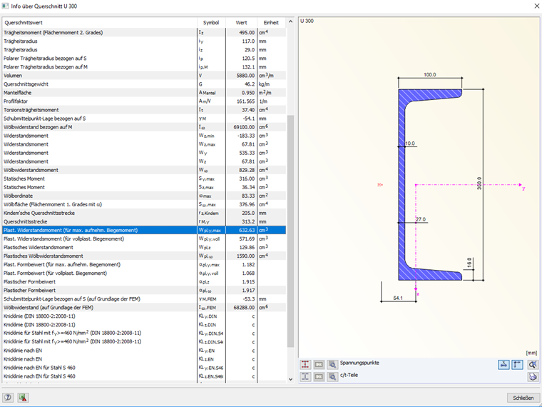
FAQ 004472 EN
Why is there a fully plastic section modulus Zfull and a maximum plastic section modulus Zmax displayed for some cross-sections?
Answer
The fully plastic section modulus Zfull is related to the full-plastic bending moment Mpl,full. For Mpl,full, there is only one internal force available in the respective direction. It is not possible to increase this internal force, even if the cross-section is not perfectly plastic.
On the other hand, the maximum plastic bending moment Mpl,max related to the maximum plastic section modulus Zmax refers to the perfectly plastic state of the cross-section. In this case, the interaction of the internal forces in the y- and z-direction is possible.
Keywords
Fully plastic Section modulus Perfectly plastic Plastic Bending moment
Downloads
Contact us
Did you find your question?
If not, contact us via our free e-mail, chat, or forum support, or send us your question via the online form.
Recommended Events
Timber Beam and Surface Structures | Part 1: Modeling, Load Input, Combinatorics
Webinar 4 May 2021 2:00 PM - 3:00 PM CEST
Eurocode 3 | Steel structures according to DIN EN 1993-1-1
Online Training 6 May 2021 8:30 AM - 12:30 PM CEST
Eurocode 2 | Concrete structures according to DIN EN 1992-1-1
Online Training 12 May 2021 8:30 AM - 12:30 PM CEST
Eurocode 5 | Timber structures according to DIN EN 1995-1-1
Online Training 20 May 2021 8:30 AM - 12:30 PM CEST
RFEM | Structural dynamics and earthquake design according to EC 8
Online Training 2 June 2021 8:30 AM - 12:30 PM CEST
Stability Design in Steel Construction with RFEM and RSTAB
Webinar 1 December 2020 2:00 PM - 2:45 PM CET
Videos
Models to Download
Knowledge Base Articles

New
CSA S16:19 Stability Considerations and the New Annex O.2
Structure stability is not a new phenomenon when referring to steel design. The Canadian steel design standard CSA S16 and the most recent 2019 release is no exception.
Screenshots
Product Features Articles

SHAPE-THIN determines the effective cross-sections according to EN 1993-1-3 and EN 1993-1-5 for cold-formed sections. You can optionally check the geometric conditions for the applicability of the standard specified in EN 1993‑1‑3, Section 5.2.
The effects of local plate buckling are considered according to the method of reduced widths and the possible buckling of stiffeners (instability) is considered for stiffened sections according to EN 1993-1-3, Section 5.5.
As an option, you can perform an iterative calculation to optimize the effective cross-section.
You can display the effective cross-sections graphically.
Read more about designing cold-formed sections with SHAPE-THIN and RF-/STEEL Cold-Formed Sections in this technical article: Design of a Thin-Walled, Cold-Formed C-Section According to EN 1993-1-3.
Frequently Asked Questions (FAQ)
- Which cross-sections can I design with the "RF‑/STEEL Cold-Formed Sections" add-on module?
- I get the message "Torsion available -> no stability analysis possible". Why does this appear and what can I do?
-
Why are my steel members not being designed for stability in RF-STEEL AISC?
- My section is classified as Class 4 and non-designable in RF-/STEEL CSA. However, my manual calculation shows a different class. Why the difference?
- I have defined temperature loads, strain loads, or a precamber. As soon as I modify stiffnesses, the deformations are no longer plausible.
- Can the properties, such as B. the cross -section or the surface thickness as well as the material of a surface of an existing element for a new element?
- How can I model and design a crane runway girder with Dlubal Software?
- I am trying to manually check the deformations from the CRANEWAY add-on module. However, I obtain great deviations. How to explain the differences?
- What should be considered when using a failure of columns under tension in the RF‑/DYNAM Pro – Equivalent Loads add-on module?
- Why is there no stability analysis displayed in the results despite the activation of the stability analysis in RF‑/STEEL EC3?
Customer Projects
Associated Products