The structural analysis software RFEM 6 is the basis of a modular software system. The main program RFEM 6 is used to define structures, materials, and loads of planar and spatial structural systems consisting of plates, walls, shells, and members. The program also allows you to create combined structures as well as to model solid and contact elements.
RSTAB 9 is a powerful analysis and design software for 3D beam, frame, or truss structure calculations, reflecting the current state of the art and helping structural engineers meet requirements in modern civil engineering.
Do you often spend too long calculating cross-sections? Dlubal Software and the RSECTION stand-alone program facilitate your work by determining section properties of various cross-sections and performing a subsequent stress analysis.
Do you always know where the wind is blowing from? From the direction of innovation, of course! With RWIND 2, you have a program at your side that uses a digital wind tunnel for the numerical simulation of wind flows. The program simulates these flows around any building geometry and determines the wind loads on the surfaces.
Are you looking for an overview of snow load zones, wind zones, and seismic zones? Then you are in the right place. Use the Geo-Zone Tool to determine quickly and efficiently snow loads, wind speeds, and seismic data according to ASCE 7‑16 and other international standards.
Would you like to try out the capabilities of the Dlubal Software programs? You have the opportunity to do so! The free 90-day full version allows you to thoroughly test all our programs.
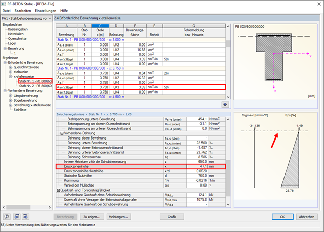
After the calculation, you can switch to result window "2.4 Required Reinforcement by x‑Location" in the add-on module RF‑CONCRETE Members (for RFEM 5) or CONCRETE (for RSTAB 8).
Here, you can select a certain result row for a particular design and x-location (upper table in Window 2.4). Then, you can evaluate the intermediate results in the lower table of this window. This covers "Neutral Axis Depth x", for example. The location of the neutral axis for the selected design location is displayed in the graphic on the right of Window 2.4.
Furthermore, you can display the distribution of the neutral axis depth along the member length graphically in the model or in "Result Diagrams on Member".