


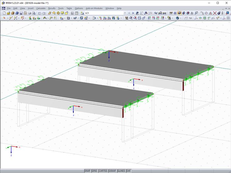
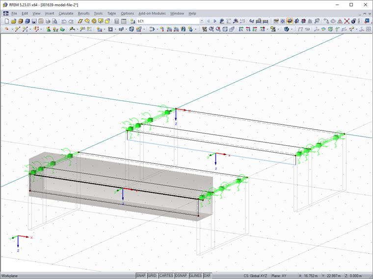
Since modeling such a surface-based rib with the result member is significantly more complicated than creating a member of the "rib" type, the following program in EXCEL-VBA will convert the member-based rib into a surface model, including the result member.
To transform a rib into a surface model, the following steps are necessary:
- Reading out rib parameters (cross-section, orientation, and so on)
- Creating a rib surface
- Creating a result beam
- Deleting the rib member
In the following text, we will show excerpts from the entire source code as examples. You can download the complete code at the end of this article.
Reading out Rib Parameters
You have the option to select the rib to be transformed by selecting it from the program interface. To do this, it is necessary to work with the EnableSelections function. As long as EnableSelections is activated with true, only selected elements are read from RFEM. The readout of the selected member looks like this.
'   get interface of active model
Set iMod = iApp.GetActiveModel

'   get interface of (structural) model data
Dim iModData As RFEM5.IModelData2
Set iModData = iMod.GetModelData

'   get selected member
iModData.EnableSelections True

Dim mems() As RFEM5.Member
Dim selMem As RFEM5.Member
mems = iModData.GetMembers
selMem = mems(0)

iModData.EnableSelections False
The following parameters are required for the rib modeling:
- Rib cross-section, surface numbers, and effective widths
- Rib orientation
- Rib material
In RFEM, a rib is a member type. When you utilize the programming via the COM interface, you have to get the data of a rib via two different interfaces. On one hand, there is the interface for the member and on the other hand, there is the interface for the rib. The interface to a rib can be obtained via IModelData.GetRib. GetRib expects the rib number contained in the member via Member.RibNo.
'   get parameters of rib
'   #####################
Dim iRb As RFEM5.IRib
Set iRb = iModData.GetRib(selMem.RibNo, AtNo)

Dim selRb As RFEM5.Rib
selRb = iRb.GetData

Dim rbCrsc As RFEM5.RibCrossSection
rbCrsc = iRb.GetRibCrossSection
The interface to the rib offers two different elements: the general rib data via the Rib Structure and the rib cross-section data via RibCrossSection. Rib contains the surface numbers, the position of the rib, and the effective widths. RibCrossSection contains the description and the dimensions of the internal rib cross-section, which is also used by RF-CONCRETE Members (ITCU).
In addition, the orientation is required, which is available via the local axis system of the member. You access the axis system via the interface to the member. The IMemer.GetLocalCoordinateSystem function returns the CoordinateSystem structure.
Dim cosy As RFEM5.CoordinateSystem
cosy = iModData.GetMember(selMem.no, AtNo).GetLocalCoordinateSystem(0#).GetData
GetLocalCoordinateSystem still expects the x-location of the member, which has been set to 0.0 or the start here. In addition to the mentioned parameters, the material of the member is also required, which can be obtained via the cross-section of the member.
Dim selCrsc As RFEM5.CrossSection
selCrsc = iModData.GetCrossSection(selMem.StartCrossSectionNo, AtNo).GetData
Creating Rib Surface
The program is initially created only for straight ribs on the positive z-side. Since the rib can also be at oblique planes, you should create the surface using the member orientation. The variable cosy for the local member axis system includes the direction vector for the local z-axis cosy.AxisZ with its three values, x, y, and z. This vector is normalized so that, multiplied by the height of the rib, it indicates the distance and direction of the bottom edge of the rib. For the boundary lines of the rib surface, this vector is multiplied by the rib height and added to the start and end nodes. This results in the two end nodes of the bottom edge line of the rib surface. Note the following: the rib height also includes half the surface thickness of the effective width. For simplification, only the surface thickness of the first side (-y in the local axis system) from the rib cross-section is used (UpperLeftFlangeThickness). After the nodes are available, you can generate the boundary lines and the rib surface.
'   create/calculate nodes
'   ######################
Dim nodes() As RFEM5.Node
nodes = selNodes
nodes(0).no = index_n + 1
nodes(1).no = index_n + 2
Dim h_rib As Double
h_rib = (rbCrsc.Depth - rbCrsc.UpperLeftFlangeThickness / 2)
nodes(0).X = nodes(0).X + h_rib * cosy.AxisZ.X
nodes(0).Y = nodes(0).Y + h_rib * cosy.AxisZ.Y
nodes(0).Z = nodes(0).Z + h_rib * cosy.AxisZ.Z
nodes(1).X = nodes(1).X + h_rib * cosy.AxisZ.X
nodes(1).Y = nodes(1).Y + h_rib * cosy.AxisZ.Y
nodes(1).Z = nodes(1).Z + h_rib * cosy.AxisZ.Z

'   create lines
'   ############
Dim lines(0 To 2) As RFEM5.RfLine
lines(0).no = index_l + 1
lines(1).no = index_l + 2
lines(2).no = index_l + 3
lines(0).NodeList = str(selNodes(0).no) + "," + str(nodes(0).no)
lines(1).NodeList = str(selNodes(1).no) + "," + str(nodes(1).no)
lines(2).NodeList = str(nodes(0).no) + "," + str(nodes(1).no)

'   create surface
'   ##############
Dim surf As RFEM5.Surface
surf.BoundaryLineCount = 4
surf.BoundaryLineList = str(selLine.no) + "," + str(lines(0).no) + "," + str(lines(2).no) + "," + str(lines(1).no)
surf.Comment = "rib"
surf.GeometryType = PlaneSurfaceType
surf.MaterialNo = selCrsc.MaterialNo
surf.Thickness.Type = ConstantThicknessType
surf.Thickness.Constant = rbCrsc.WebThickness
surf.StiffnessType = StandardStiffnessType
surf.no = index_s + 1
The variables index_n, index_l, index_s each contain the last index of the respective element from RFEM. See the source code to download at the end of this article to determine the indices.
Creating Result Beam
The result beam, like the rib, consists of two elements: the standard structure Member, and the additional data ResultBeam. You can only modify the additional data via the interface to the member, so you have to create the member first; then you can transfer the data via the IMember interface. Since the member usually has to be eccentric, the start and end nodes are created directly in the shear center without member eccentricity. The eccentricity is saved in RibCrossSection. Thus, you can copy the start and end nodes of the original rib and use them as a basis. You can move the copied nodes to the correct location using the direction vectors y and z from the local member axis system. For a later design, the result beam also requires a cross-section, which is first copied from the original rib. Then, the cross-section description is imported from RibCrossSection and CrossSection.TextID is emptied, otherwise it will be used for the cross-section creation instead of the string from CrossSection.Description.
' create nodes for result member and calculate eccentricity
Dim resNodes() As RFEM5.Node
resNodes = selNodes
resNodes(0).no = index_n + 3
resNodes(1).no = index_n + 4
resNodes(0).X = selNodes(0).X + rbCrsc.Eccentricity.Z * cosy.AxisZ.X + rbCrsc.Eccentricity.Y * cosy.AxisY.X
resNodes(0).Y = selNodes(0).Y + rbCrsc.Eccentricity.Z * cosy.AxisZ.Y + rbCrsc.Eccentricity.Y * cosy.AxisY.Y
resNodes(0).Z = selNodes(0).Z + rbCrsc.Eccentricity.Z * cosy.AxisZ.Z + rbCrsc.Eccentricity.Y * cosy.AxisY.Z
resNodes(1).X = selNodes(1).X + rbCrsc.Eccentricity.Z * cosy.AxisZ.X + rbCrsc.Eccentricity.Y * cosy.AxisY.X
resNodes(1).Y = selNodes(1).Y + rbCrsc.Eccentricity.Z * cosy.AxisZ.Y + rbCrsc.Eccentricity.Y * cosy.AxisY.Y
resNodes(1).Z = selNodes(1).Z + rbCrsc.Eccentricity.Z * cosy.AxisZ.Z + rbCrsc.Eccentricity.Y * cosy.AxisY.Z
' create line
Dim resLine As RFEM5.RfLine
resLine.no = index_l + 4
resLine.NodeCount = 2
resLine.Type = PolylineType
resLine.NodeList = str(resNodes(0).no) & "," & str(resNodes(1).no)
' create cross section
Dim resCrsc As RFEM5.CrossSection
resCrsc = selCrsc
resCrsc.description = rbCrsc.description
resCrsc.no = index_c + 1
resCrsc.TextID = ""
' create member
Dim resMem As RFEM5.Member
resMem.LineNo = resLine.no
resMem.no = index_m + 1
resMem.Type = ResultBeamType
resMem.StartCrossSectionNo = resCrsc.no
resMem.Rotation = selMem.Rotation
' send data to RFEM
' ####################
iModData.PrepareModification
iModData.SetNodes nodes
iModData.SetLines lines
iModData.SetSurface surf
iModData.SetNodes resNodes
iModData.SetLine resLine
iModData.SetCrossSection resCrsc
iModData.SetMember resMem
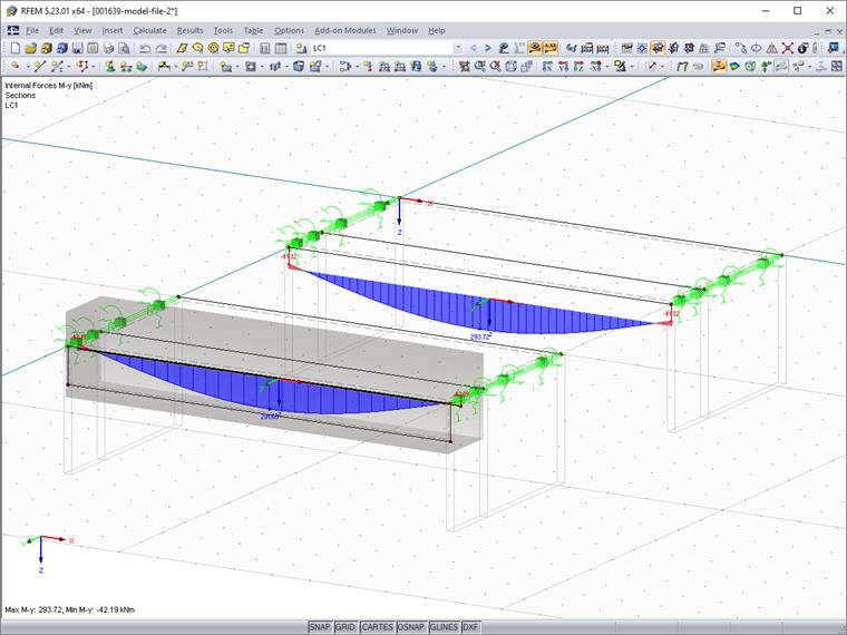
iModData.FinishModificationAfter creating the member (also nodes, lines, cross-section, and surface), you have to determine and transfer the parameters for the result beam. A result beam integrates the internal forces of other elements (members, surfaces, solids) and transforms them into member internal forces according to their position. To include the correct elements, a result beam has two basic options. You can specify the elements to be integrated and additionally limit the integration range by means of a solid (cylinder or cuboid). In this case, the number of the new rib surface and the numbers of the surfaces of the effective widths, if any, are used. As the integration area, the cuboid is selected, which (viewed locally) can be defined in the +/- y- and +/- z- directions. The values from RibCrossSection are used again as values. Please note that in the case of a missing effective width, an integration width must still be used so that the floor above the rib is correctly integrated. The additional width must, therefore, be half the surface thickness.
'   set result beam parameters
'   ##########################
Dim resBeam As RFEM5.ResultBeam
Dim iResBeam As RFEM5.IResultBeam
Set iResBeam = iModData.GetMember(resMem.no, AtNo).GetExtraData
resBeam = iResBeam.GetData

'       set integrated elements
If selRb.SurfaceNoSide1 Then
    resBeam.IncludeSurfaces = str(selRb.SurfaceNoSide1) & ","
End If
If selRb.SurfaceNoSide2 Then
    resBeam.IncludeSurfaces = resBeam.IncludeSurfaces & str(selRb.SurfaceNoSide2) & ","
End If
resBeam.IncludeSurfaces = resBeam.IncludeSurfaces & str(surf.no)

'       set integration area
resBeam.Integrate = WithinCuboidGeneral
Dim resBeamParam(0 To 3) As Double
'   +y, -y, +z, -z
If selRb.WidthSide2 Then
    resBeamParam(0) = selRb.WidthSide2 - rbCrsc.Eccentricity.Y
Else
    resBeamParam(0) = 0.5 * rbCrsc.WebThickness - rbCrsc.Eccentricity.Y
End If
If selRb.WidthSide1 Then
    resBeamParam(1) = selRb.WidthSide1 + rbCrsc.Eccentricity.Y
Else
    resBeamParam(1) = 0.5 * rbCrsc.WebThickness + rbCrsc.Eccentricity.Y
End If
resBeamParam(2) = rbCrsc.Depth
resBeamParam(3) = rbCrsc.Depth

resBeam.Parameters = resBeamParam

'       send new result beam parameters to RFEM
iModData.PrepareModification
iResBeam.SetData resBeam
iModData.FinishModification
Deleting Rib Member
Since the new rib was created from surfaces, you can now delete the member (the old rib). You can delete any element using the DeleteObjects function of the IModelData interface. Again, since elements are modified, you have to use a Prepare/Finish modification block.
'   Remove Rib
'##########
iModData.PrepareModification
iModData.DeleteObjects MemberObject, str(selMem.no)
iModData.FinishModification
Conclusion
In their simplicity, ribs as members cannot always cover all aspects of a more complex model. Creating a member rib is simple, and therefore, the program presented here combines the simple creation of a rib as a member with the more detailed modeling and display of a rib from surfaces. In addition to the already known elements, such as the interfaces to the member (IMember), we introduced the interface IRib, which provides access to the rib cross-section, among other things. We also read out the local axis system of a member and created the surface of the rib using the vector calculation.
Outlook for Future
There are options for refinement in the program. For example, you could include considering the rib position (top, bottom, middle). Another option would be the extension to tapered ribs or even ribs on curved lines.
