


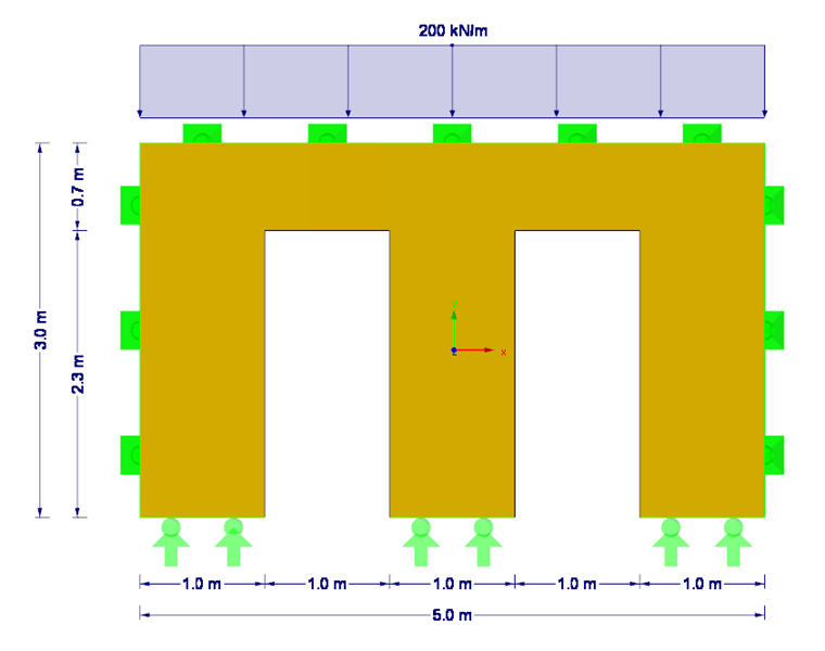
This example presents a flexural buckling analysis of a quadrilateral cross-laminated timber wall with two door openings (see Figure 1). In this case, the governing case is the wall section between the doors.
According to [1], the flexural buckling analysis can be performed using the equivalent member method with internal forces according to the linear static analysis in compliance with Section 6.3.2, or by considering imperfections in compliance with Section 5.4.4. In both cases, Section 2.2.2 must be respected. For this, the mean values of the stiffness parameters (modulus of elasticity and shear modulus) divided by the partial factor γM should be used to determine the internal forces according to the second-order analysis in compliance with 2.4.1(2)P. Furthermore, [2] NCI NA.9.3.3 defines those situations when a stability analysis must be performed according to the second-order analysis for planar structural components. If equation NA.150 is fulfilled, stability analyses may be calculated using equivalent member design as well as second-order analysis. Otherwise, the designs must be performed exclusively according to the second-order analysis.
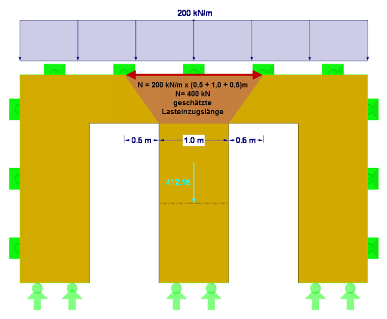
First, it is necessary to check whether equation NA.150 has been fulfilled. This requires the acting axial force Nd, the bending stiffness E∙I along the local y-axis, the partial factor γM for cross-laminated timber, and the effective length of the respective wall section between the doors. The load application length is set approximately at 0.5 m + 1.0 m + 0.5 m = 2.0 m. Thus, the resulting compressive force Nd is 200 kN/m ∙ 2 m = 400 kN (without consideration of self-weight). Alternatively, the exact determination of the compressive force considering the self-weight can be obtained by using the section resultant forces in RFEM (see Figure 2). Due to the orthotropy and the self-weight, the resulting compressive force is 412 kN.
Bending stiffness can be deducted directly from the stiffness matrix of the surface (see Figure 3). Here, the wall surface by Stora Enso of the CLT type CLT 100 C5s is selected. The resulting bending stiffness in the y-direction is 826.16 kNm ∙ 1.0 m = 826.16 kNm².
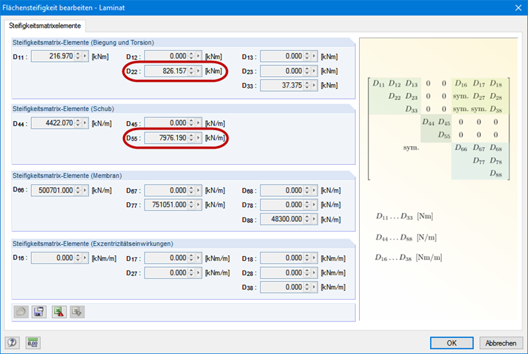
The partial factor of 1.3 is applied in accordance with [2]. To determine the effective lengths, the shear stiffness in the y-direction should also be considered for the cross-laminated timber (see Figure 3). The effective length factor β of 1.0 is used according to Euler case 2.
The delimitation criterion is not met with 2.55 > 1.00; therefore, the stability analysis according to the second-order analysis must be performed. Since an almost linear member is analyzed, both methods will be explained in my upcoming articles.
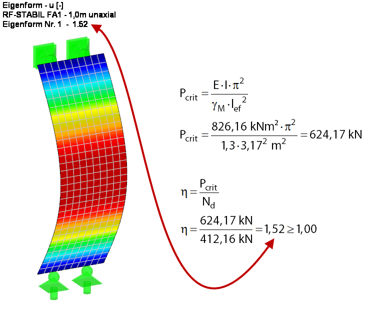
In order to better understand the buckling problem in this case, the critical buckling load and the critical load factor are first determined according to the linear static analysis for the wall section on the ideal, simply supported beam (see Figure 4). For this, the critical load factor is determined analytically and by using the RF-STABILITY add-on module. For the FEM solution, a load case without self-weight is created and the resulting load is applied directly. The stiffness reduction related to the partial safety factor γM is activated in the calculation parameters of the load case. The result of both calculations is exactly the same.
Taking into account the additional stiffnesses resulting from the door lintel, the overall system has a slightly larger critical load factor of 1.67, as would be expected.
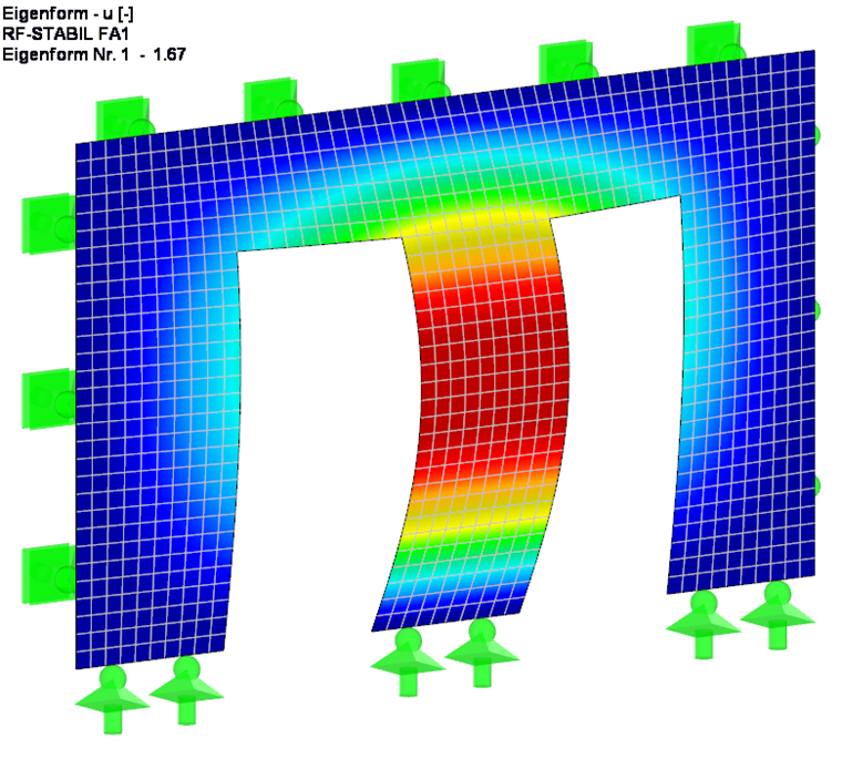
This critical load factor indicates the number by which the load must be multiplied so that the model under the associated load becomes unstable (buckling). Consequently: A critical load factor smaller than 1.00 means that the structure is unstable. Only a positive critical load factor greater than 1.00 means that the load due to the predefined axial forces multiplied by this factor leads to the buckling failure of the stable structure. However, the stability analysis according to 1995-1-1 must also be performed, because the critical load factor and the critical buckling load are unreliable, since influences of imperfections (no member or surface is straight), eccentricities of the load introduction, and material behavior deviating from Hooke's law are not taken into account. The designs are explained in the next article of this series.