748 Results
View Results:
Sort by:
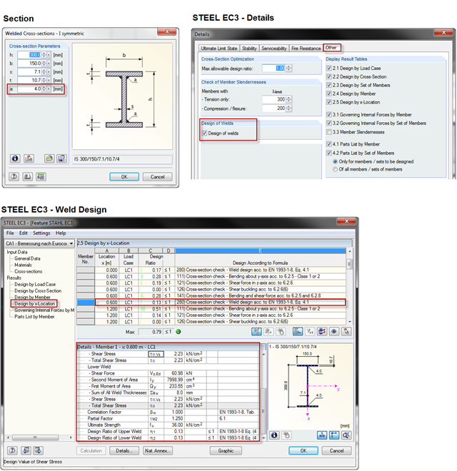
When using a welded profile, weld seam verification can also be carried out in RF-/STEEL EC3 as part of the design. The program performs the typical designs according to EN 1993‑1‑8.
If you want to simulate, for example, the failure of particular structural members, you can use the "Modify stiffness" function.

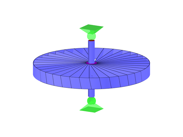
In RFEM, you have the option to create and analyze cables using sheaves. For this, use the "Cable on Pulleys" member type. It is ideal for pulley systems, where the longitudinal forces are transferred via sheaves.
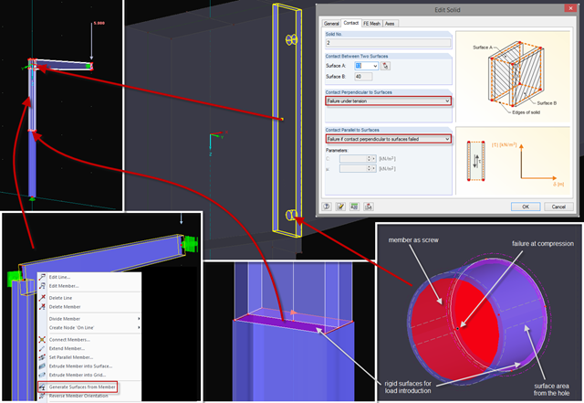
Sometimes, a detailed examination is needed of problematic areas of a joint or the stiffness of a frame joint. The following tips can help you with this. As an example, a frame joint was modeled using RF‑FRAME‑JOINT Pro and members, and used as a basis.
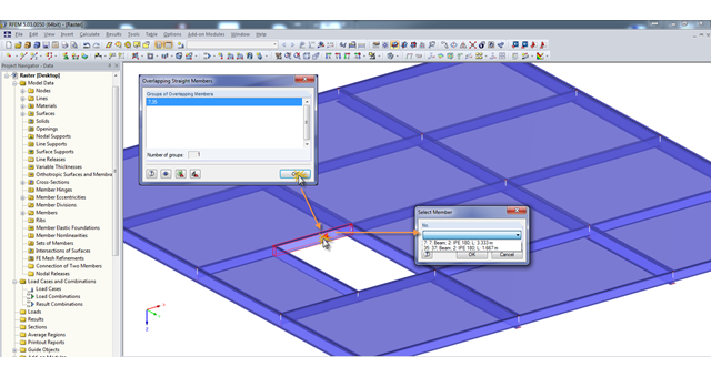
A modell check allows you to find overlapping members, among other things. However, this targeted selection could cause some minor problems. Therefore, there is a selection window now available, which appears when you click on one of the elements. This appears by clicking on one of the elements. Additional information helps you to select the correct member.
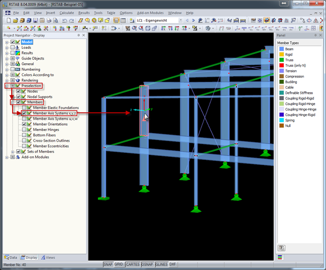
The local coordinate system of a member is particularly important when defining member end releases and member nonlinearities. The definitions follow the orientation of the axes. You can temporarily adjust the visibility of these member axes by means of preselection.
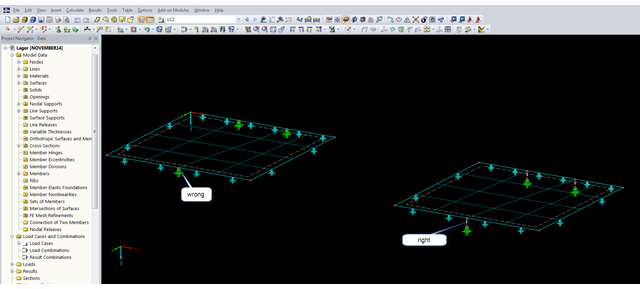
When defining real support conditions, it is always necessary to combine linear and nonlinear support conditions. This way, a beam resting on a wall can transfer compression forces to the wall and the line support (wall) will not take over the lifting forces. These forces should be carried by screws, for example, which are defined as a linear nodal support.
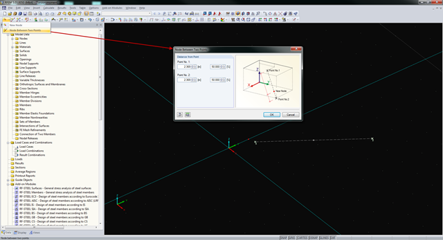
In RFEM and RSTAB, you can create nodes not only by means of coordinates, but also by means of existing nodes. You can use the "Node Between Two Points" function to create a node located on an imaginary line connecting two nodes. You can enter the distance as a percentage or according to the relative lengths.
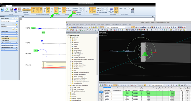
The equivalent loads determined in RF-TENDON due to prestress are transferred in RFEM as member loads or as line loads. A member load is used for member types with their own stiffness; a line load is used for member types without their own stiffness. In order to understand which values of the concentrated loads are to be transferred from RF‑TENDON to RFEM, you should use the following display settings: ~ Reference of the loads to the global coordinate system (GCS), ~ Load display: "Point"
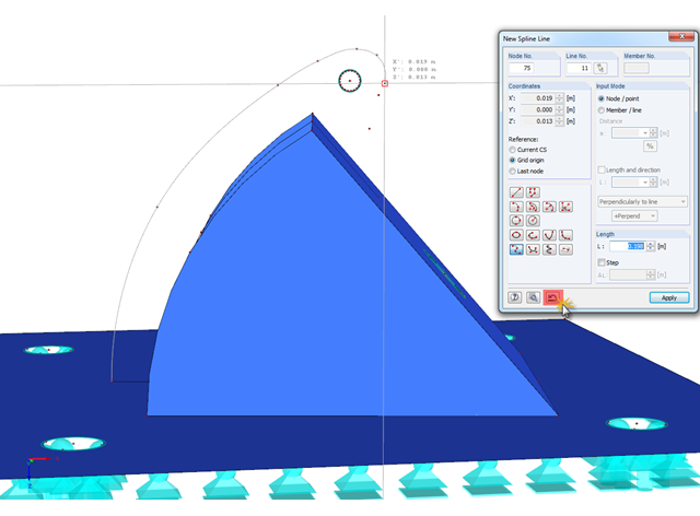
In RFEM, if you want to display a curved geometry (preferably in one continuous line), you can use splines or NURBS, for example. When modeling, you should pick the individual nodes one after another. If a mistake is made, you can go back using the special Undo function in the "New Spline Line" window. Thus, it is not necessary to enter the entire continuous line again.