
Use RWIND 2 Pro to easily apply a permeability to a surface. All you need is the definition of
- the Darcy coefficient D,
- the inertial coefficient I, and
- the length of the porous medium in the direction of flow L,
to define a pressure boundary condition between the front and back of a porous zone. Due to this setting, you obtain the flow through this zone with a two-part result display on both sides of the zone area.
But that's not all. Furthermore, the generation of a simplified model recognizes permeable zones and takes into account the corresponding openings in the model coating. Can you waive an elaborate geometric modeling of the porous element? Understandable – we have good news for you then! With a pure definition of the permeability parameters, you can avoid complex geometric modeling of the porous element. Use this feature to simulate permeable scaffolding, dust curtains, mesh structures, and so on.
More Information
Do you already know the editor for mesh refinement control? It is a great help for your work! Why? It's easy – it gives you the following options:
- Graphic visualization of the areas with mesh refinements
- Mesh refinement of zones
- Deactivating the standard 3D solid mesh refinement with transversion into the corresponding manual 3D mesh refinements.
These options help you to formulate a suitable rule for meshing the entire model, even for the models with unusual dimensions. Use the editor to efficiently define small model details on large buildings or detailed meshing areas in the coating area of the model. You will be amazed!
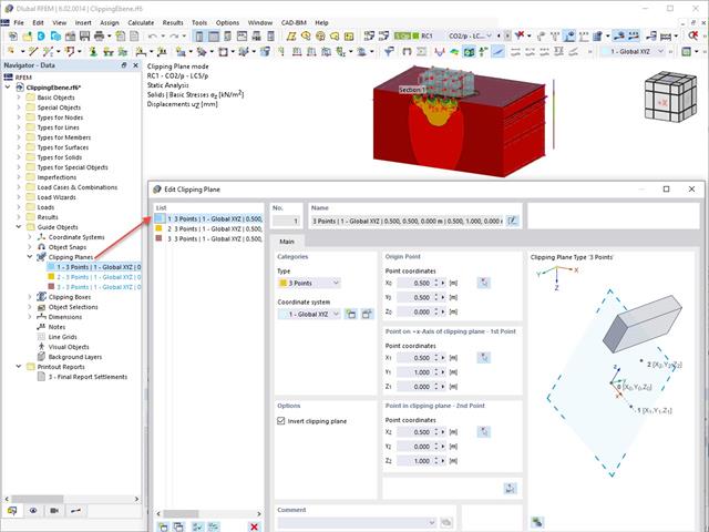
This feature also contributes to the clearly-arranged display of your results. Clipping planes are intersecting planes that you can place freely throughout the model. The zone in front of or behind the plane is consequently hidden in the display. This way, you can clearly and simply show the results in an intersection or a solid, for example.
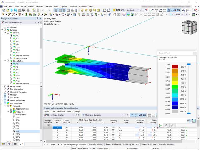
For stress-strain analyses, it is possible to define gray zones for nonrelevant value ranges in the result panel.
.png?mw=640&hash=342149908caead326e60e26a2b5d05f7f46825cb)
Are you familiar with the Tsai-Wu material model? It combines plastic and orthotropic properties, which allows for special modeling of materials with anisotropic characteristics, such as fiber-reinforced plastics or timber.
If the material is plastified, the stresses remain constant. The redistribution is carried out according to the stiffnesses available in the individual directions. The elastic area corresponds to the Orthotropic | Linear Elastic (Solids) material model. For the plastic area, the yielding according to Tsai-Wu applies:
All strengths are defined positively. You can imagine the stress criterion as an elliptical surface within a six-dimensional space of stresses. If one of the three stress components is applied as a constant value, the surface can be projected onto a three-dimensional stress space.
If the value for fy(σ), according to the Tsai-Wu equation, plane stress condition, is smaller than 1, the stresses are in the elastic zone. The plastic area is reached as soon as fy (σ) = 1; values greater than 1 are not allowed. The model behavior is ideal-plastic, which means there is no stiffening.

- Calculation of stationary incompressible turbulent wind flow using the SimpleFOAM solver from the OpenFOAM® software package
- Numerical scheme according to the first and second order
- Turbulence models RAS k-ω and RAS k-ε
- Consideration of surface roughness depending on model zones
- Model design via VTP, STL, OBJ, and IFC files
- Operation via bidirectional interface of RFEM or RSTAB for importing model geometries with standard-based wind loads and exporting wind load cases with probe-based printout report tables
- Intuitive model changes via drag & drop and graphical adjustment assistance
- Generation of a shrink-wrap mesh envelope around the model geometry
- Consideration of environmental objects (buildings, terrain, and so on)
- Height-dependent description of the wind load (wind speed and turbulence intensity)
- Automatic meshing depending on a selected depth of detail
- Consideration of layer meshes near the model surfaces
- Parallelized calculation with optimal utilization of all processor cores of a computer
- Graphical output of the surface results on the model surfaces (surface pressure, Cp coefficients)
- Graphical output of the flow field and vector results (pressure field, velocity field, turbulence – k-ω field, and turbulence – k-ε field, velocity vectors) on Clipper/Slicer planes
- Display of 3D wind flow via animated streamline graphics
- Definition of point and line probes
- Multilingual user interface (German, English, Czech, Spanish, French, Italian, Polish, Portuguese, Russian, and Chinese)
- Calculations of several models in one batch process
- Generator for creating rotated models to simulate different wind directions
- Optional interruption and continuation of the calculation
- Individual color panel per result graphic
- Display of diagrams with separate output of results on both sides of a surface
- Output of the dimensionless wall distance y+ in the mesh inspector details for the simplified model mesh
- Determination of the shear stress on the model surface from the flow around the model
- Calculation with an alternative convergence criterion (you can select between the residual types pressure or flow resistance in the simulation parameters)

By solving the numerical flow problem, you can obtain the following results on and around the model:
- Pressure on structure surface
- Coefficient Cp distribution on the structure surfaces
- Pressure field about the structure geometry
- Velocity field about the structure geometry
- Turbulence k-ω field about the structure geometry
- Turbulence k-ε field about the structure geometry
- Velocity vectors about the structure geometry
- Streamlines about the structure geometry
- Forces on member-shaped structures that were originally generated from member elements
- Convergence diagram
- Direction and size of the flow resistance of the defined structures
Despite this amount of information, RWIND 2 remains clearly arranged, as is typical for the Dlubal programs. You can specify freely definable zones for a graphic evaluation. Voluminously displayed flow results about the structure geometry are often confusing – you know the problem for sure. That's why RWIND Basic provides freely movable section planes for the separate display of the "solid results" in a plane. For the 3D branched streamline result, you have an option to select between a static and an animated display in the form of moving line segments or particles. This option helps you to represent the wind flow as a dynamic effect.
You can export all results as a picture or, especially for the animated results, as a video.
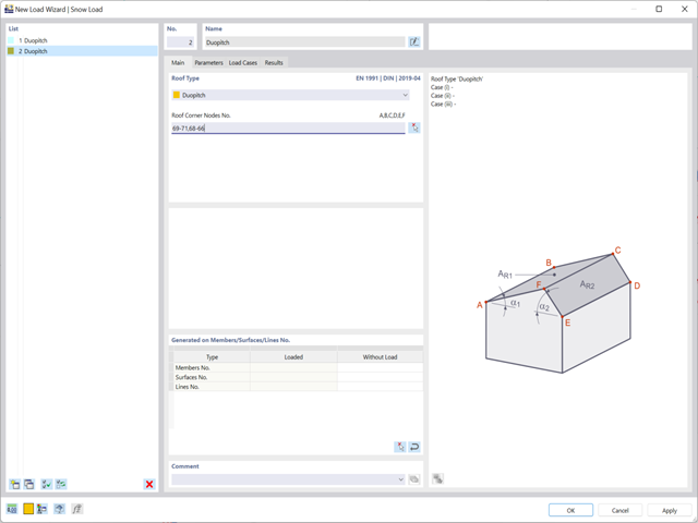
Discover the new functions of the snow and wind load wizards:
- Loading of hybrid models made of members and surfaces (RFEM only)
- Connection to the Geo-Zone Tool (depending on the global construction site definition)
- Switching off surface sides
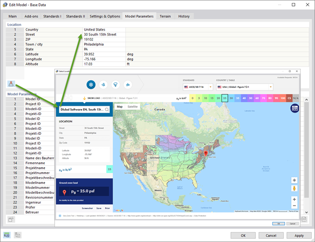
Always keep an eye on the natural conditions of your construction site by defining it on a digital map. The address data (including the altitude) as well as the snow load zone, wind zone, and seismic zone are imported automatically. The load wizard also uses this data.
The map is also displayed with the construction site marked in the "Model Parameters" tab.
Go to Explanatory Video
Take a look at the "My Account" category. This is where your customer data, such as address, licensed programs, and add-ons are managed. It also takes you straight to the Dlubal website. Find out about the latest news there, use online services such as "Snow Load Zones, Wind Zones and Earthquake Zones", or get helpful information from the FAQ database.

The standards already specify the approximation methods (for example, deformation calculation according to EN 1992‑1‑1, 7.4.3, or ACI 318‑19, 24.3.2.5) that you need for your deformation calculation. In this case, the so-called effective stiffnesses are calculated in the finite elements in accordance with the existing limit state with / without cracks. You can then use these effective stiffnesses to determine the deformations by means of another FEM calculation.
Consider a reinforced concrete cross-section for the calculation of the effective stiffnesses of the finite elements. Based on the internal forces determined for the serviceability limit state in RFEM, you can classify the reinforced concrete cross-section as "cracked" or "uncracked". Do you consider the effect of the concrete between the cracks? In this case, this is done by means of a distribution coefficient (for example, according to EN 1992‑1‑1, Eq. 7.19, or ACI 318‑19, 24.3.2.5). You can assume the material behavior for the concrete to be linear-elastic in the compression and tension zone until reaching the concrete tensile strength. This procedure is sufficiently precise for the serviceability limit state.
When determining the effective stiffnesses, you can take into accout the creep and shrinkage at the "cross-section level." You don't need to consider the influence of shrinkage and creep in statically indeterminate systems in this approximation method (for example, tensile forces from shrinkage strain in systems restrained on all sides are not determined and have to be considered separately). In summary, the deformation calculation is carried out in two steps:
- Calculation of effective stiffnesses of the reinforced concrete cross-section assuming linear-elastic conditions
- Calculation of the deformation using the effective stiffnesses with FEM

- General stress analysis
- Automatic import of internal forces from RFEM/RSTAB
- Graphical and numerical output of stresses, strains, clearance, and design ratios fully integrated in RFEM/RSTAB
- User-defined specification of the limit stress
- Summary of similar structural components for the design
- Wide range of customization options for graphical output
- Clearly arranged result tables for a quick overview after the design
- Simple traceability of the results due to the complete documentation of the calculation method including all formulas
- High productivity due to the minimal amount of input data required
- Flexibility due to detailed setting options for basis and extent of calculations
- Gray zone display for unimportant value ranges (see Product Feature)

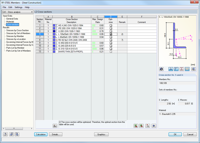
- Cross-section optimization
- Transfer of optimized sections to RFEM/RSTAB
- Design of any thin-walled section from RSECTION
- Representation of a stress diagram on a section
- Determination of normal, shear, and equivalent stresses
- Output of stress components for the individual member internal force types
- Detailed representation of stresses in all stress points
- Determination of the largest Δσ for each stress point (for example, for fatigue design)
- Colored display of stresses and design ratios for a quick overview of the critical or oversized zones
- Output of parts lists
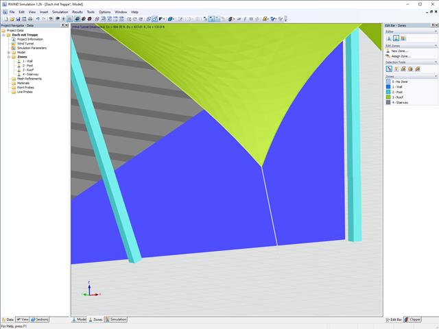
In RWIND Simulation, it is possible to divide the model in different zones. This allows for different surface roughness to be assigned to the zones. In addition, local results can be better evaluated.
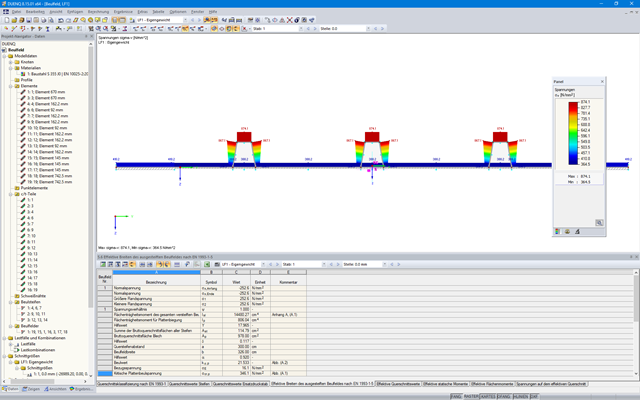
In SHAPE-THIN 8, the effective cross-section of stiffened buckling panels can be calculated according to EN 1993-1-5, Cl. 4.5.
The critical buckling stress is calculated according to EN 1993-1-5, Annex A.1 for buckling panels with at least 3 longitudinal stiffeners, or according to EN 1993-1-5, Annex A.2 for buckling panels with one or two stiffeners in the compression zone. The design for torsional buckling safety is also performed.
- Cross-section optimization
- Transfer of optimized sections to RFEM/RSTAB
- Design of any thin-walled cross-section from SHAPE-THIN
- Representation of a stress diagram on a section
- Determination of normal, shear, and equivalent stresses
- Stress results of individual internal forces types
- Detailed representation of stresses in all stress points
- Determination of the largest Δσ for each stress point (for example, for fatigue design)
- Colored display of stresses and design ratios for a quick overview of the critical or oversized zones
- Parts lists and quantity surveying
- Design of the following geometrical types:
- Single-span beams with and without cantilevers
- Continuous beams with and without cantilevers
- Hinged girder system (Gerber beams) with and without cantilevers
- Automatic generation of wind and snow loads
- Automatic creation of required combinations for the ultimate and serviceability limit states, as well as fire resistance design
- For design according to EC 5 (EN 1995), the following National Annexes are available:
-
 DIN EN 1995-1-1/NA:2013-08 (Germany)
 -
 NBN EN 1995-1-1/ANB:2012-07 (Belgium)
 -
 DK EN 1995-1-1/NA:2011-12 (Denmark)
 -
 SFS EN 1995-1-1/NA:2007-11 (Finland)
 -
 NF EN 1995-1-1/NA:2010-05 (France)
 -
 UNI EN 1995-1-1/NA:2010-09 (Italy)
 -
 NEN EN 1995-1-1/NB:2007-11 (Netherlands)
 -
 ÖNORM B 1995-1-1:2015-06 (Austria)
 -
 PN EN 1995-1-1/NA:2010-09 (Poland)
 -
 SS EN 1995-1-1 (Sweden)
 -
 STN EN 1995-1-1/NA:2008-12 (Slovakia)
 -
 SIST EN 1995-1-1/A101:2006-03 (Slovenia)
 -
 CSN EN 1995-1-1:2007-09 (Czech Republic)
 -
 BS EN 1995-1-1/NA:2009-10 (the United Kingdom)
-
- Consideration of optimization options by user specifications according to the respective standard:
- Shear force reduction of single loads near support
- Shear force reduction of load introduction at the cross-section top point
- Moment redistribution in support zone
- Reduction of torsional stress by means of user-defined entry of moment
- Increase of bending stiffnesses for flat-ended or edgewise bending strains
- Simple geometry input with illustrative graphics
- Extensive material library for both standards
- Optional extension of material library by further materials
- Extensive library of permanent loads
- Allocation of framework to service classes and specification of service class categories
- Determination of design ratios, support forces, and deformations
- Info icon indicating successful or failed design
- Color reference scales in result tables
- Direct data export to MS Excel
- Program languages: English, German, Czech, Italian, Spanish, French, Portuguese, Polish, Chinese, Dutch, and Russian
- Verifiable printout report, including all required designs. Printout report available in many output languages; for example, English, German, French, Italian, Spanish, Russian, Czech, Polish, Portuguese, Chinese, and Dutch.
- Direct import of stp files from various CAD programs
- Full integration in RFEM/RSTAB with import of geometry and load case data
- Automatic selection of members for design according to specified criteria (e.g. only vertical members)
- In connection with the extension EC2 for RFEM/RSTAB, you can perform the design of reinforced concrete compression elements according to the method based on nominal curvature in compliance with EN 1992 -1‑1:2004 (Eurocode 2) and the following National Annexes:
-
DIN EN 1992-1-1/NA/A1:2015-12 (Germany)
-
ÖNORM B 1992-1-1:2018-01 (Austria)
-
Belgium NBN EN 1992-1-1 ANB:2010 for design at normal temperature, and NBN EN 1992-1-2 ANB:2010 for fire resistance design (Belgium)
-
 BDS EN 1992-1-1:2005/NA:2011 (Bulgaria)
 -
EN 1992-1-1 DK NA:2013 (Denmark)
-
NF EN 1992-1-1/NA:2016-03 (France)
-
SFS EN 1992-1-1/NA:2007-10 (Finland)
-
UNI EN 1992-1-1/NA:2007-07 (Italy)
-
 LVS EN 1992-1-1:2005/NA:2014 (Latvia)
 -
 LST EN 1992-1-1:2005/NA:2011 (Lithuania)
 -
 MS EN 1992-1-1:2010 (Malaysia)
 -
NEN-EN 1992-1-1+C2:2011/NB:2016 (Netherlands)
-
 NS EN 1992-1 -1:2004-NA:2008 (Norway)
 -
PN EN 1992-1-1/NA:2010 (Poland)
-
 NP EN 1992-1-1/NA:2010-02 (Portugal)
 -
 SR EN 1992-1-1:2004/NA:2008 (Romania)
 -
SS EN 1992-1-1/NA:2008 (Sweden)
-
 SS EN 1992-1-1/NA:2008-06 (Singapore)
 -
STN EN 1992-1-1/NA:2008-06 (Slovakia)
-
SIST EN 1992-1-1:2005/A101:2006 (Slovenia)
-
 UNE EN 1992-1-1/NA:2013 (Spain)
 -
CSN EN 1992-1-1/NA:2016-05 (Czech Republic)
-
BS EN 1992-1-1:2004/NA:2005 (United Kingdom)
-
 TKP EN 1992-1-1:2009 (Belarus)
 -
 CYS EN 1992-1-1:2004/NA:2009 (Cyprus)
-
- In addition to the National Annexes (NA) listed above, you can define a specific NA, applying user-defined limit values and parameters.
- Optional consideration of creep
- Diagram-based determination of buckling lengths and slenderness from the restraint ratios of columns
- Automatic determination of ordinary and unintentional eccentricity from additionally available eccentricity according to the second-order analysis
- Design of monolithic structures and precast elements
- Analysis with regard to the standard reinforced concrete design
- Determination of internal forces according to the linear static analysis and the second-order analysis
- Analysis of governing design locations along the column due to existing loading
- Output of required longitudinal and stirrup reinforcement
- Fire resistance design according to the simplified method (zone method) according to EN 1992-1-2 allowing the fire resistance design of brackets.
- Fire resistance design with optional longitudinal reinforcement design according to DIN 4102-22:2004 or DIN 4102-4:2004, Table 31
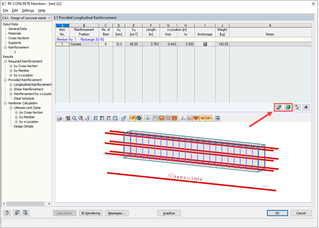
- Longitudinal and link reinforcement proposal with graphic display in 3D rendering
- Summary of design ratios, including all design details
- Graphical representation of relevant design details in RFEM/RSTAB work window

SHAPE-THIN calculates all relevant cross‑section properties, including plastic limit internal forces. Overlapping areas are set close to reality. If cross-sections consist of different materials, SHAPE‑THIN determines the effective cross‑section properties with respect to the reference material.
In addition to the elastic stress analysis, you can perform the plastic design including interaction of internal forces for any cross‑section shape. The plastic interaction design is carried out according to the Simplex Method. You can select the yield hypothesis according to Tresca or von Mises.
SHAPE-THIN performs a cross-section classification according to EN 1993-1-1 and EN 1999-1-1. For steel cross-sections of cross-section class 4, the program determines effective widths for unstiffened or stiffened buckling panels according to EN 1993-1-1 and EN 1993-1-5. For aluminum cross-sections of cross-section class 4, the program calculates effective thicknesses according to EN 1999-1-1.
Optionally, SHAPE‑THIN checks the limit c/t-values in compliance with the design methods el‑el, el‑pl, or pl‑pl according to DIN 18800. The c/t-zones of elements connected in the same direction are recognized automatically.
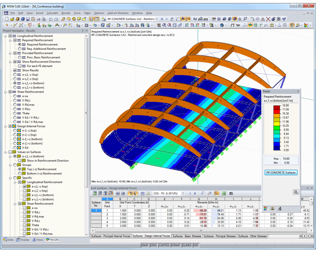
Before the calculation starts, you should check the input data using the program function. Then, the CONCRETE add‑on module searches the results of relevant load cases, load as well as result combinations. If these cannot be found, RSTAB starts the calculation to determine the required internal forces.
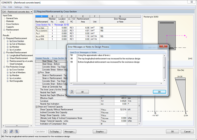
Considering the selected design standard, the required reinforcement areas of the longitudinal and the shear reinforcement as well as the corresponding intermediate results are calculated. If the longitudinal reinforcement determined by the ultimate limit state design is not sufficient for the design of the maximum crack width, it is possible to increase the reinforcement automatically until the defined limit value is reached.
The design of potentially unstable structural components is possible using a nonlinear calculation. According to a respective standard, different approaches are available.
The fire resistance design is performed according to a simplified calculation method in compliance with EN 1992‑1‑2, 4.2. The module uses the zone method mentioned in Annex B2. Furthermore, you can consider the thermal strains in the longitudinal direction and the thermal precamber additionally arising from asymmetrical effects of fire.
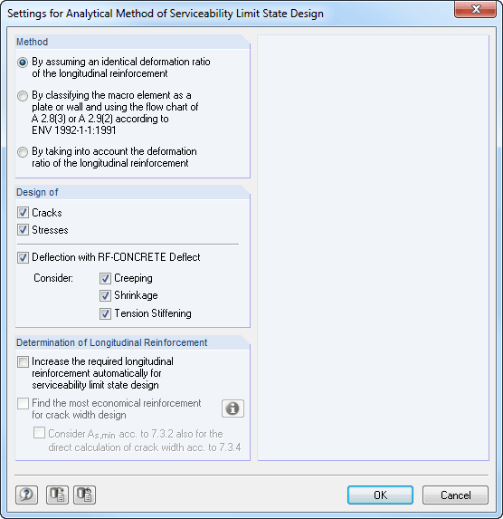
The deformation analysis according to the approximation method defined in standards (for example, deformation analysis according to EN 1992‑1‑1, 7.4.3) applies to the calculation of "effective stiffnesses" in the finite elements in accordance with the existing limit state of the concrete with or without cracks. These stiffnesses are used to determine the surface deformation by repeated FEM calculation.
The effective stiffness calculation of finite elements takes into account a reinforced concrete cross-section. Based on the internal forces determined for the serviceability limit state in RFEM, the program classifies the reinforced concrete cross-section as 'cracked' or 'uncracked'. If the tension stiffening at a section should be considered as well, a distribution coefficient (according to EN 1992-1-1, Eq. 7.19, for example) is used. The material behavior for the concrete is assumed to be linear-elastic in the compression and tension zone until the concrete tensile strength is reached. This is reached exactly in the serviceability limit state.
When determining the effective stiffnesses, creep and shrinkage are taken into account at the "cross-section level". The influence of shrinkage and creep in statically indeterminate systems is not taken into account in this approximation method (for example, tensile forces from shrinkage strain in systems restrained on all sides are not determined and must be considered separately). In summary, RF-CONCRETE Deflect calculates deformations in two steps:
- Calculation of effective stiffnesses of the reinforced concrete cross-section assuming linear-elastic conditions
- Calculation of the deformation using the effective stiffnesses with FEM
- Import of results from RSTAB
- Integrated material and cross-section library
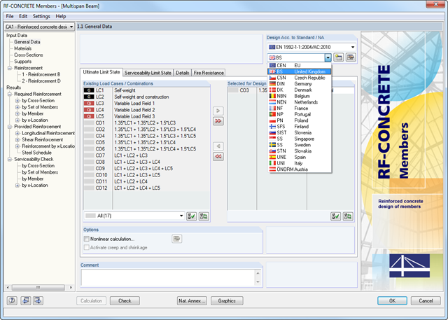
- The module extension EC2 for RSTAB enables design of reinforced concrete according to EN 1992-1-1 (Eurocode 2) and the following National Annexes:
-
DIN EN 1992-1-1/NA/A1:2015-12 (Germany)
-
ÖNORM B 1992-1-1:2018-01 (Austria)
-
Belgium NBN EN 1992-1-1 ANB:2010 for design at normal temperature, and NBN EN 1992-1-2 ANB:2010 for fire resistance design (Belgium)
-
BDS EN 1992-1-1:2005/NA:2011 (Bulgaria)
-
EN 1992-1-1 DK NA:2013 (Denmark)
-
NF EN 1992-1-1/NA:2016-03 (France)
-
SFS EN 1992-1-1/NA:2007-10 (Finland)
-
UNI EN 1992-1-1/NA:2007-07 (Italy)
-
LVS EN 1992-1-1:2005/NA:2014 (Latvia)
-
LST EN 1992-1-1:2005/NA:2011 (Lithuania)
-
MS EN 1992-1-1:2010 (Malaysia)
-
NEN-EN 1992-1-1+C2:2011/NB:2016 (Netherlands)
- NS EN 1992-1 -1:2004-NA:2008 (Norway)
-
PN EN 1992-1-1/NA:2010 (Poland)
-
NP EN 1992-1-1/NA:2010-02 (Portugal)
-
SR EN 1992-1-1:2004/NA:2008 (Romania)
-
SS EN 1992-1-1/NA:2008 (Sweden)
-
SS EN 1992-1-1/NA:2008-06 (Singapore)
-
STN EN 1992-1-1/NA:2008-06 (Slovakia)
-
SIST EN 1992-1-1:2005/A101:2006 (Slovenia)
-
UNE EN 1992-1-1/NA:2013 (Spain)
-
CSN EN 1992-1-1/NA:2016-05 (Czech Republic)
-
BS EN 1992-1-1:2004/NA:2005 (United Kingdom)
-
CPM 1992-1-1:2009 (Belarus)
-
CYS EN 1992-1-1:2004/NA:2009 (Cyprus)
-
- In addition to the National Annexes (NA) listed above, you can also define a specific NA, applying user‑defined limit values and parameters.
- Optional presetting of partial safety factors, reduction factors, neutral axis depth limitation, material properties, and concrete cover
- Determination of longitudinal, shear, and torsional reinforcement
- Design of tapered members
- Cross‑section optimization
- Representation of minimum and compression reinforcement
- Determination of editable reinforcement proposal
- Crack width analysis with optional increase of the required reinforcement in order to keep the defined limit values of the crack width analysis
- Nonlinear calculation with consideration of cracked cross‑sections (for EN 1992‑1‑1:2004 and DIN 1045‑1:2008)
- Considering tension stiffening
- Considering creep and shrinkage
- Deformations in cracked sections (state II)
- Graphical representation of all result diagrams
- Fire resistance design according to the simplified method (zone method) according to EN 1992‑1‑2 for rectangular and circular cross‑sections. Thus, fire resistance design of brackets is possible as well.
- Determination of longitudinal, shear, and torsional reinforcement
- Representation of minimum and compression reinforcement
- Determination of neutral axis depth, concrete and steel strains
- Design of member sections affected by bending about two axes
- Design of tapered members
- Determination of deformation in state II, for example according to EN 1992-1-1, 7.4.3
- Considering tension stiffening
- Considering creep and shrinkage
- Precise breakdown of reasons for failed design
- Design details of all design locations for better traceability of reinforcement determination
- Options to optimize cross‑sections
- Visualization of concrete section with reinforcement in 3D rendering
- Output of complete steel schedule
- Fire resistance design according to the simplified method (zone method) according to EN 1992‑1‑2 for rectangular and circular cross‑sections
- Optional extension of the RF‑CONCRETE Members add‑on module with a nonlinear calculation of frameworks for the ultimate and serviceability limit states. The extension enables the design of potentially unstable structural components by means of a nonlinear calculation, or a nonlinear deformation analysis of 3D frameworks. Find more information under the product description of the RF-CONCRETE NL add‑on module.
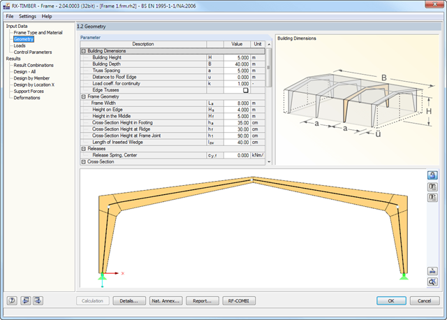
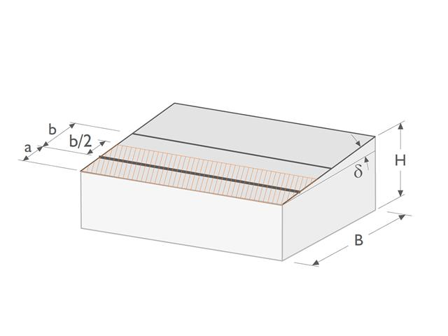
There are various options available for frame modeling. Graphical representations facilitate the geometry input. Modifications are updated automatically. Basic dimensions as well as geometrical data are entered in tables. During the input, the program checks the conditions required for the beam creation (for example, lamellas forming a curve) according to the defined standard. The most important geometry parameters are updated and displayed.
The relevant timber grade of the material can be selected from the material library. All material grades for glulam, hardwood, poplar and softwood timber specified in EN 1995-1-1 are available. Furthermore, it is possible to generate a strength class with user-defined material properties in order to extend the library. Permanent loads (for example, roof structure) can also be entered using the comprehensive and extensible material library.
Generators integrated in RX-TIMBER Purlin allow for convenient generation of various wind and snow load cases. By clicking the information buttons, the map of wind and snow zones for the relevant country is displayed. The corresponding zone can be selected with a double-click. Load cases can be checked graphically. However, you can enter load specifications manually as well. According to the generated loads, the program automatically creates combinations for the ultimate and serviceability limit states as well as for fire resistance design in the background. The generated combinations can be considered or adjusted by user-defined specifications.
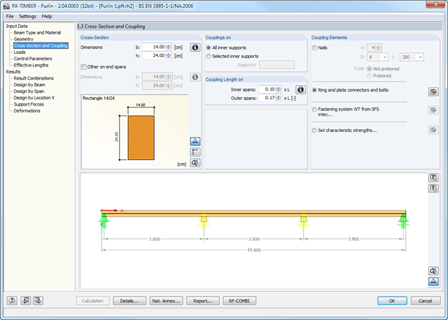
There are various options available for beam modeling. A roof type determines the exact purlin location for wind and snow generation.
Two beam types are available: continuous beam and purlin. If you select the continuous beam, it is possible to define several hinge conditions of the beam. If you select the purlin, it is not possible to modify hinge conditions. In this case, the calculation considers a double cross-section in the coupling zone. In addition, several coupling elements are available in the purlin settings:
- Nails (prebored/not prebored)
- Ring and plate connectors and bolts
- Screw connection with fastening system WT from SFS intec
- User-defined specification using characteristic strength
The relevant timber grade of the material can be selected from the material library. All material grades for glulam, hardwood and softwood timber specified in EC 5 are available. Furthermore, you have the option to generate a strength class with user-defined material properties and thus extend the library.A comprehensive and extensible material library can also be used for entering permanent loads (for example, roof structure).
Generators integrated in RX-TIMBER Purlin allow for convenient generation of various wind and snow load cases. By clicking the information buttons, the map of wind and snow zones for the relevant country is displayed. The corresponding zone can be selected with a double-click. Load cases can be checked graphically.
However, you can enter load specifications manually as well. According to the generated loads, the program automatically creates combinations for the ultimate and serviceability limit states as well as for fire resistance design in the background.