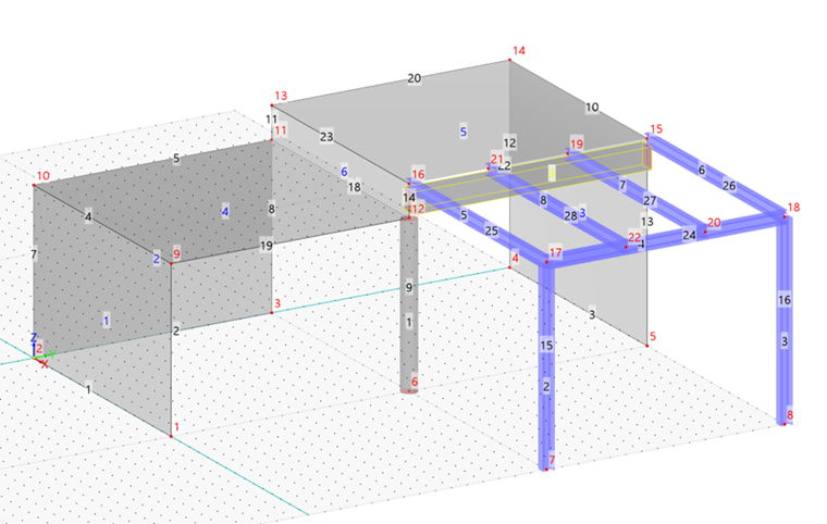
To define the downstand beam underneath the slab, double-click this line (no. 22). Then select the Member option again.
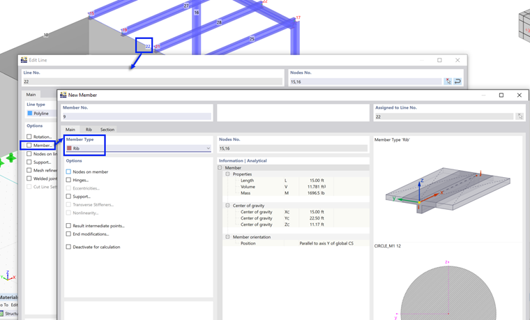
In the 'New Member' dialog box, select the Rib member type from the list.
Select the Rib tab which has been added.
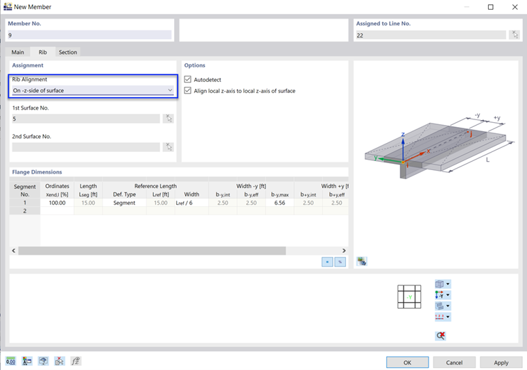
Make sure that On -z-side of surface is set in the 'Rib Alignment' area so that the rib is arranged beneath the surface (the z-axis of the related surface is pointing upwards). If this is not the case, open the list and select that option.
The circular section needs revision. Click the Section tab to adjust it.

In the 'Section with Material' area, click the
![]() button to create a new section. The 'New Section' dialog box opens.
button to create a new section. The 'New Section' dialog box opens.
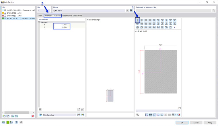
Check that the parametric massive rectangle
![]() is selected (1). Then go to the Parametric - Massive I tab (2). Enter the width b as 12.0 in and the depth h as 16.0 in to define the geometry of the rib member (3).
is selected (1). Then go to the Parametric - Massive I tab (2). Enter the width b as 12.0 in and the depth h as 16.0 in to define the geometry of the rib member (3).
With a depth of 16.0 in and half of the surface thickness of 4.0 in, the elevation of 20.0 in between the slabs is shown, i.e. the downstand beam rests on top of the circular column.
Click OK three times to close all dialog boxes.