


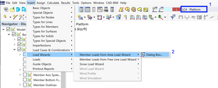
Set LC4 on the toolbar (1).
To define the surface load on the beams of the platform, it is possible to calculate the load values on each member and apply them one by one. An easier way is to utilize the Load Wizards function that was activated in the 'Base Data' dialog box (see the Add-ons for analysis and design image).
On the Insert menu, point to Load Wizards, Member Loads from Area Load Wizard, and click Dialog Box (2).
The 'New Load Wizard' dialog box opens.
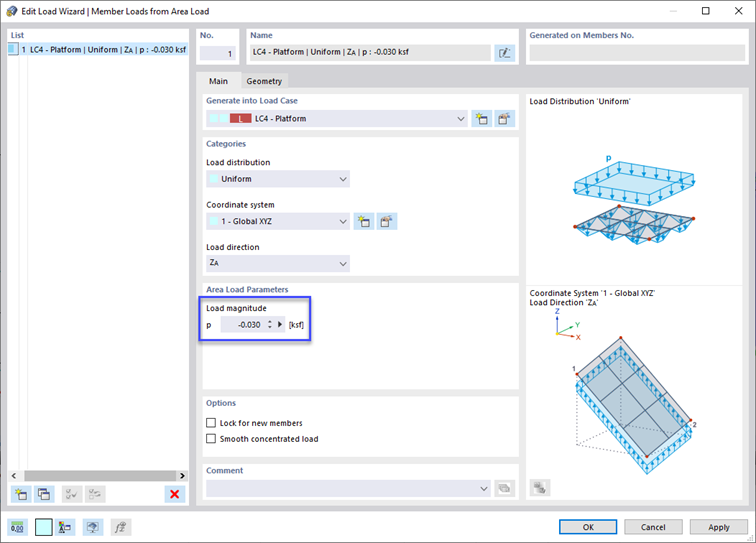
The 'Uniform' load distribution and the 'ZA' load direction (“global Z on true area”) is preset, which is appropriate. In the 'Area Load Parameters' area, enter the surface load of -0.030 ksf.
Click the Geometry tab to define the area of load application.
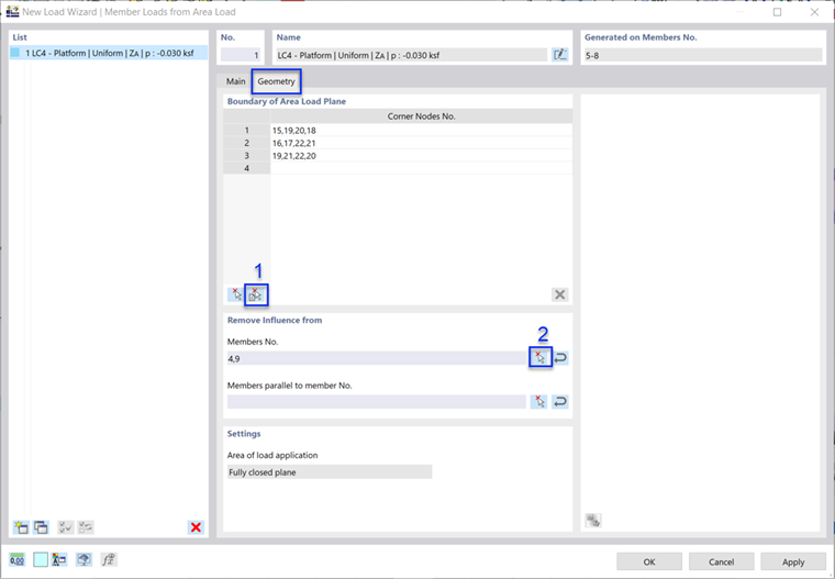
To define the 'Boundary of Area Load Plane' graphically, click the
![]() button (1). The view is changed so that you can define the load area by selecting its “cells”.
button (1). The view is changed so that you can define the load area by selecting its “cells”.
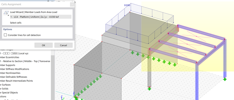
Cells are fully closed areas between members and lines. They are symbolized by X-diagonals.
To select the three relevant cells, click them one after another or draw a window over the platform. Then click OK to return to the 'New Load Wizard' dialog box.
The live load acts on the platform girders only, not on the downstand beam and frame girder. To exclude those two members for the loads to be converted, click the
![]() button (2) in the 'Remove influence from' area (see the Geometry tab image). The view is changed again for you to select the members in the graphics.
button (2) in the 'Remove influence from' area (see the Geometry tab image). The view is changed again for you to select the members in the graphics.
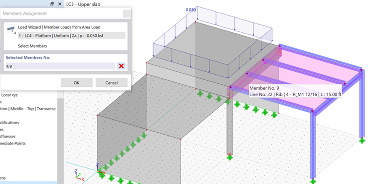
Select the downstand beam (no. 4) and the frame girder (no. 9) so that their numbers are listed in the 'Selected Members' area. Then click OK.
Close the load wizard by clicking OK. The area load is applied to the platform.
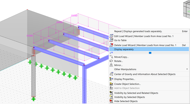
To check the proportional load values of each member, the display of the load needs to be adjusted. Right-click the area load to open its shortcut menu. From there, select the Display separately option.
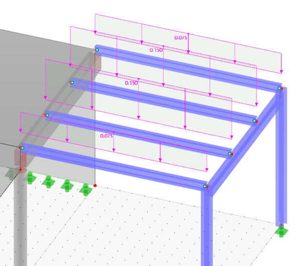
The center girders of the platform have double loads. The downstand beam and frame girder are without loads.
Checking load data
As before, all input of the loads can be checked in the navigator and tables: Select the Loads (for LC1 through LC3) or Load Wizards (for LC4) from the items list in the table toolbar. Then set the load case in the list next to it and select the table sheet; for example, Surface Loads.
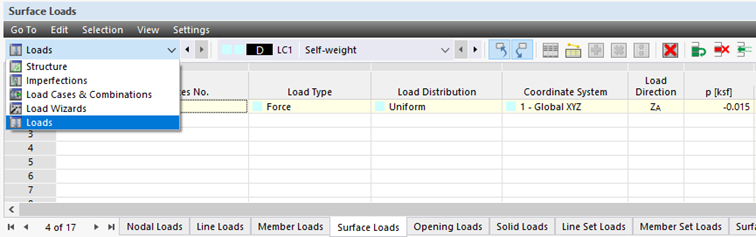
The model objects and assigned load values can be modified in those tables, if required.