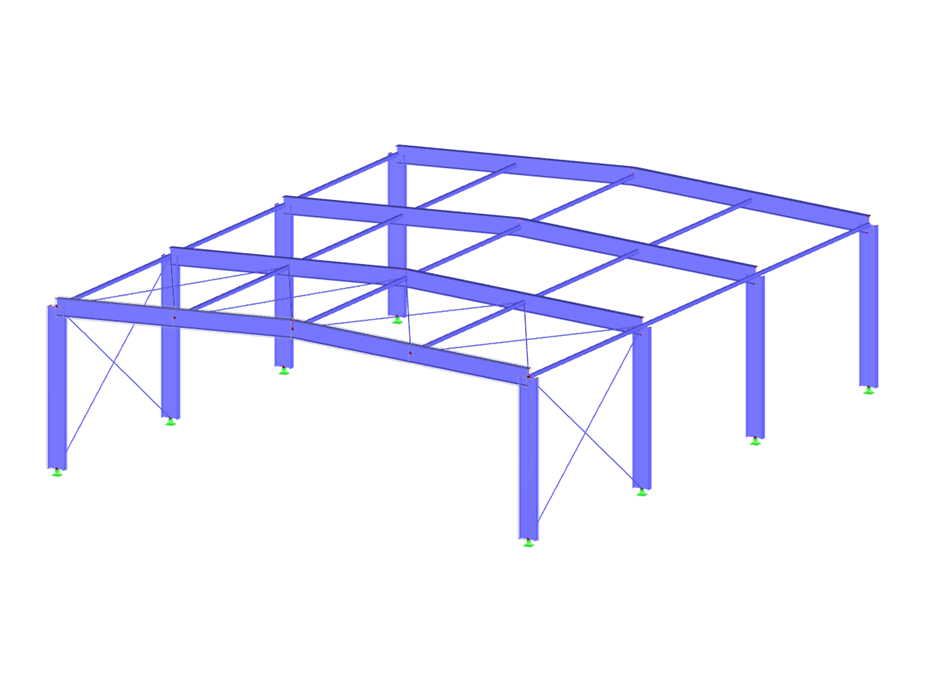
You can download this structural model to use it for training purposes or for your projects. However, we do not assume any guarantee or liability for the accuracy or completeness of the model.
Frame Structure
Model to Download
Description
Model Used in
Keywords
Frame structure Equivalent member method General method EC 3 Eurocode 3
Write Comment...
Write Comment...
Disclaimer
Recommended Events
Videos
Models to Download
Knowledge Base Articles

New
Design of a welded truss
This technical article deals with the component and cross-section designs of a welded truss in the ultimate limit state. Furthermore, the deformation analysis in the serviceability limit state is described.
Screenshots
Product Features Articles

Material Database with Steels According to the Australian Standard AS/NZS 4600:2005
The material database in RFEM, RSTAB and SHAPE-THIN contains steels according to the Australian standard AS/NZS 4600:2005.Frequently Asked Questions (FAQ)
- What is the difference between the RF‑/STEEL and RF‑/STEEL EC3 add-on modules?
- I perform a stability analysis of a beam for lateral-torsional buckling. Why is the modified reduction factor χLT,mod used in the design according to DIN EN 1993‑1‑1, 6.3.3 Method 2? Is it possible to deactivate this?
- I need to define different types of lateral intermediate restrains for a single element in RF-/STEEL EC3. Is this possible?
- I compare the flexural buckling design according to the equivalent member method and the internal forces according to the linear static analysis with the stress calculation according to the second-order analysis including imperfections. The differences are very large. What is the reason?
- Why are the equivalent member designs grayed out in the Stability tab when activating the plastic designs by using the partial internal force method (RF‑/STEEL Plasticity)?
-
I design a set of members by using the equivalent member method in RF‑/STEEL EC3, but the calculation fails. The system is unstable, delivering the message "Non-designable - ER055) Zero value of the critical moment on the segment."
What could be the reason? - I cannot see any members if the RF-/STEEL EC3 add-on module is selected as a "load case," why?
- What does the load application point in RF-/STEEL EC3 Warping Torsion refer to?
- To which axes refer the support rotations and support eccentricities in RF‑/STEEL EC3 Warping Torsion?
- Why do I get different design results for a load combination (CO) and a result combination (RC) in STEEL EC3 in spite of the same internal forces?