Home Downloads & Info References Customer Projects John W. Olver Design Building University of Massachusetts, USA
John W. Olver Design Building University of Massachusetts, USA
Customer Project
In September 2017, the Design Building at the University of Massachusetts in Amherst was completed. The $52 million project is one of the largest timber structures in the USA and one of the largest timber-concrete composite projects in the world.
Investor |
University of Massachusetts Building Authority Boston, MA, USA www.umass.edu |
Architect |
Leers Weinzapfel Associates Architects Boston, MA, USA www.lwa-architects.com |
Structural Analysis |
Equilibrium Consulting Inc. Vancouver, BC, Canada www.eqcanada.com |
Model
The four-story university building with a floor area of 8,129 m² includes three faculties on the premises of UMass Amherst with offices, studios, lecture halls and laboratories.
Structure and Design
The building is largely exposed and consists of 5 ply CLT concrete composite floor panels supported by a glulam post and beam structure.
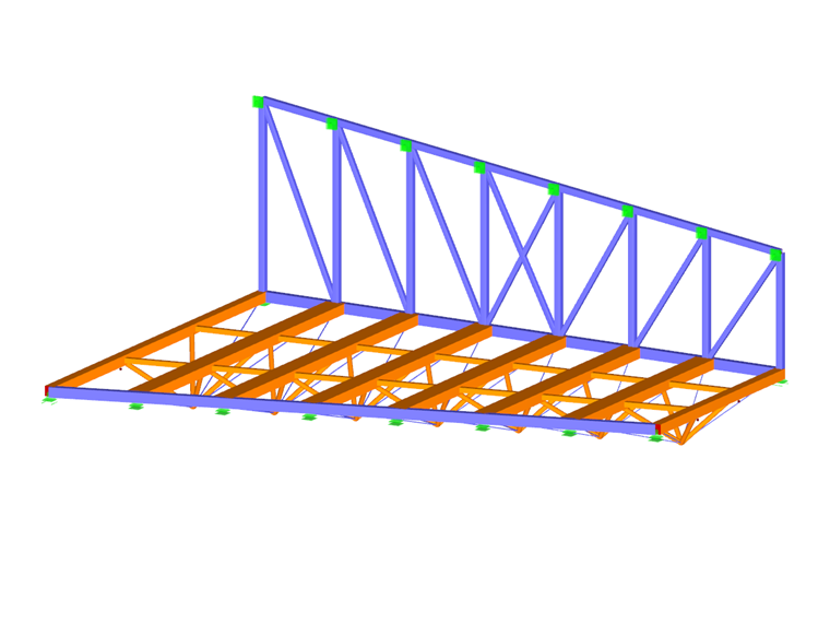
The engineers of Equilibrium Consulting Inc. modeled and analyzed two main building components utilizing RFEM including the “zipper trusses” with adjacent steel trusses as well as the timber-concrete composite section trusses.
Each zipper truss converges four 9‑inch diameter timber struts and four varying diameter steel bars at a single point to transfer the load back to the upper glulam beams. The 12‑foot wide trusses vary in span length from 35 feet to 60 feet along with a varying depth between 7 feet and 9 feet.
For the timber-concrete composite section truss design, multiple steel connectors were modeled along the truss length to initiate the composite action between the concrete deck and the glulam timber beam. The timber-concrete composite section truss clear span extends a total length of 25 feet.
The Design Building sets a new standard of quality and performance for institutional timber construction in the USA and demonstrates how state-of-the-art timber construction can meet the demanding performance requirements of large, post-secondary educational facilities.
Project Location
Contact us
Do you have questions or need advice?
Contact our free e-mail, chat, or forum support or find various suggested solutions and useful tips on our FAQ page.
Recommended Events
Eurocode 5 | Timber structures according to EN 1995-1-1
Online Training 03/17/2021 8:30 AM - 12:30 PM CET
Eurocode 3 | Steel structures according to DIN EN 1993-1-1
Online Training 03/18/2021 8:30 AM - 12:30 PM CET
Eurocode 3 | Steel structures according to DIN EN 1993-1-1
Online Training 05/06/2021 8:30 AM - 12:30 PM
Eurocode 2 | Concrete structures according to DIN EN 1992-1-1
Online Training 05/11/2021 8:30 AM - 12:30 PM
Eurocode 5 | Timber structures according to DIN EN 1995-1-1
Online Training 05/20/2021 8:30 AM - 12:30 PM
RFEM | Structural dynamics and earthquake design according to EC 8
Online Training 06/02/2021 8:30 AM - 12:30 PM
Videos
KB 000628 | Modeling Downstand Beams in Cross-Laminated Timber Constructions with Ribs
Length 0:41 min
KB 000585 | Calculation of warping springs for consideration in lateral -torsional buckling analy...
Length 1:30 min
Models to Download
Knowledge Base Articles

New
Modeling Downstand Beams in Cross-Laminated Timber Constructions with Ribs
This time, we want to look at modeling downstand beams by means of ribs.
Screenshots
3D models in RFEM: Zipper trusses with adjacent steel trusses (top) and timber-concrete composite section trusses with modeled steel connectors (bottom) (© Equilibrium Consulting Inc.)
External Pressure Coefficients, Cp, for Domed Roofs with a Circular Base (according to Figure 27.3-2 [1])
The model is constructed by means of parameters for geometry and loads and regenerates when the parameters are changed.
Product Features Articles

SHAPE-THIN | Cold-Formed Sections
SHAPE-THIN determines the effective cross-sections according to EN 1993-1-3 and EN 1993-1-5 for cold-formed sections. You can optionally check the geometric conditions for the applicability of the standard specified in EN 1993‑1‑3, Section 5.2.
The effects of local plate buckling are considered according to the method of reduced widths and the possible buckling of stiffeners (instability) is considered for stiffened sections according to EN 1993-1-3, Section 5.5.
As an option, you can perform an iterative calculation to optimize the effective cross-section.
You can display the effective cross-sections graphically.
Read more about designing cold-formed sections with SHAPE-THIN and RF-/STEEL Cold-Formed Sections in this technical article: Design of a Thin-Walled, Cold-Formed C-Section According to EN 1993-1-3.
Frequently Asked Questions (FAQ)
- Why do I get large differences for the design of a longitudinally stiffened buckling panel in comparison with the German and Austrian National Annex?
- How can I create a curved or arched section?
- How can I perform the stability analysis in RF‑/STEEL EC3 for a flat bar supported on edges, such as 100/5? Although the cross-section is rotated by 90° in RFEM/RSTAB, it is displayed as lying flat in RF‑/STEEL EC3.
- How are the signs for the release results of a line release and line hinges interpreted?
- How are hot-dip galvanized components considered for fire resistance in the RF‑/STEEL EC3 add-on module?
- How is the rotational stiffness of a buckling stiffener determined in PLATE‑BUCKLING?
- After the design with RF‑/TIMBER Pro, I optimized a cross-section. Why is the utilization of the optimized cross-section exceeded now?
- Is it possible to design the support pressure or the compression perpendicular to the grain in RX‑TIMBER?
- Why are the stresses of the 90° orientation not displayed for a layer with the orthotropy direction 90° for σb,90 in RF‑LAMINATE?
- In RF‑/STEEL EC3, is the "Elastic design (also for Class 1 and Class 2 cross-sections)" option under "Details → Ultimate Limit State" considered for a stability analysis when activated?
Customer Projects