


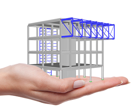
Solutions for Drilling Structures and Drilling Masts


Recommended Products for Drilling Structures and Drilling Masts

Support and Learning
We provide professional support and many services in order to help you with finding a quick and efficient solution for your projects.
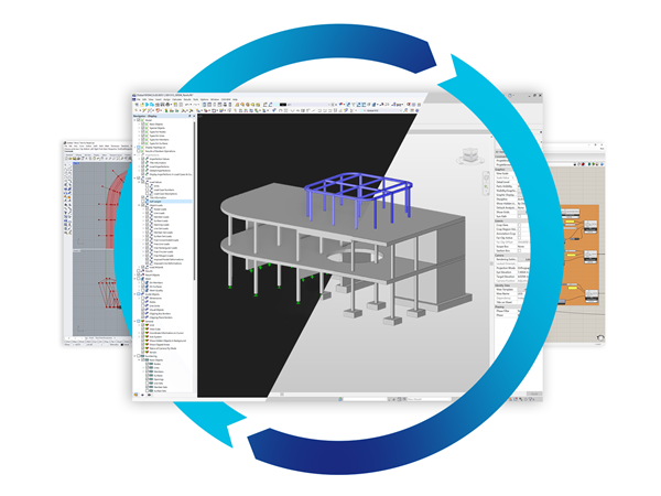
After a thorough evaluation of the solutions available on the market, our choice naturally fell on RFEM by Dlubal for calculating our three-dimensional metal structures.
This software stands out for its compliance with Eurocodes, intuitive interface, and exceptional transparency in the display of input data and results. The technical service proved to be of high quality, combining patience, competence, and responsiveness, thus reinforcing our confidence in this choice.


.png?mw=200&hash=ceabdac71454991b172d1a40faa3844b9a756ff1)

New Structure of Deep Drilling Rig
As the geothermal energy market is continuously increasing, the company BAUER Maschinen GmbH has developed a new deep drilling rig, which was used for the structural analysis done by the Dlubal Software customer Ing.-Büro H.-U. Möller from Minden, Germany. The system is used to make borings reaching to a depth of 7,000 m (22,965 ft) in the area of geothermal energy, oil, or gas.
-
Project Location
Germany
-
Software
RSTAB 8 | Structural Frame & Truss Analysis Software
.png?mw=80&hash=24e105a767cf2e175614b729c2d2fa1673e4e81b)
Technical Support | Sales Team